Welding clamping system
A clamping and clamping part technology, which is applied in the field of clamping systems for welding, can solve the problems of poor clamping stability of clamping hands and insufficient adaptability of mechanical clamping hands, and achieve the effect of improving clamping stability and applicability
- Summary
- Abstract
- Description
- Claims
- Application Information
AI Technical Summary
Problems solved by technology
Method used
Image

Examples
Embodiment Construction
[0054] The present invention is described in further detail now in conjunction with accompanying drawing. These drawings are all simplified schematic diagrams, which only illustrate the basic structure of the present invention in a schematic manner, so they only show the configurations related to the present invention.
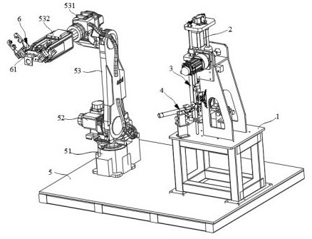
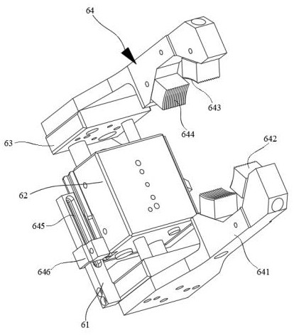
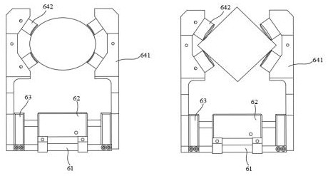
[0055] Such as Figures 1 to 14 As shown, the present invention provides a clamping system for welding, including: a console, a base, a rotating motor, a support arm and a clamping part. Wherein the console 5 is suitable for supporting the base 51; the base 51 is suitable for supporting and installing the supporting arm 53; the rotating motor 52 is suitable for driving the supporting arm 53 to rotate; the supporting arm 53 is suitable for supporting the clamping part 6, and drives the clamping part 6 to rotate ; The clamping portion 6 is suitable for grasping workpieces of different sizes and shapes. For each of the above components, a detailed description wil...
PUM
 Abstract
Description
Claims
Application Information
 - Generate Ideas
- Intellectual Property
- Life Sciences
- Materials
- Tech Scout
- Unparalleled Data Quality
- Higher Quality Content
- 60% Fewer Hallucinations
Browse by: Latest US Patents, China's latest patents, Technical Efficacy Thesaurus, Application Domain, Technology Topic, Popular Technical Reports.
© 2025 PatSnap. All rights reserved.Legal|Privacy policy|Modern Slavery Act Transparency Statement|Sitemap|About US| Contact US: help@patsnap.com