Bag type grouting soil stress active dynamic control method

A soil stress and dynamic control technology, applied in excavation, soil protection, construction, etc., can solve problems such as damage to adjacent structures, various influencing factors, and deficiencies, so as to improve accuracy, improve flexibility, and avoid excessive correction or The effect of insufficient correction

Inactive Publication Date: 2021-11-12
TIANJIN UNIV
View PDF5 Cites 5 Cited by
  • Summary
  • Abstract
  • Description
  • Claims
  • Application Information

AI Technical Summary

Problems solved by technology

[0004] 1) Passive control is often used in construction projects to ensure the safety of foundation pit structures and adjacent building structures, but passive control is to improve the performance of foundation pit enclosure support from the perspective of optimal design in the design stage of foundation pit enclosure structures. There are no active measures to ensure the safety of adjacent structures
[0005] 2) The traditional sleeve valve grouting and ordinary capsule grouting realize the volume control through the grouting amount, but due to the complex underground rock and soil environment and various influencing factors, the volume control method cannot accurately calculate the grouting amount, and the grouting amount is often judged based on experience. The amount of grout, but the actual grout amount is too high or too low, resulting in excessive protection or insufficient protection of adjacent building structures, and the expected active control effect cannot be achieved
[0006] 3) The traditional sleeve valve grouting and ordinary capsule grouting start protection and correction measures after the adjacent building structures reach the deformation warning value. Intrinsic damage to the structure cannot be repaired

Method used


Image

  • Bag type grouting soil stress active dynamic control method
  • Bag type grouting soil stress active dynamic control method
  • Bag type grouting soil stress active dynamic control method

Examples


Embodiment Construction

[0015] In order to further understand the invention content, characteristics and effects of the present invention, the following examples are given, and detailed descriptions are as follows in conjunction with the accompanying drawings:

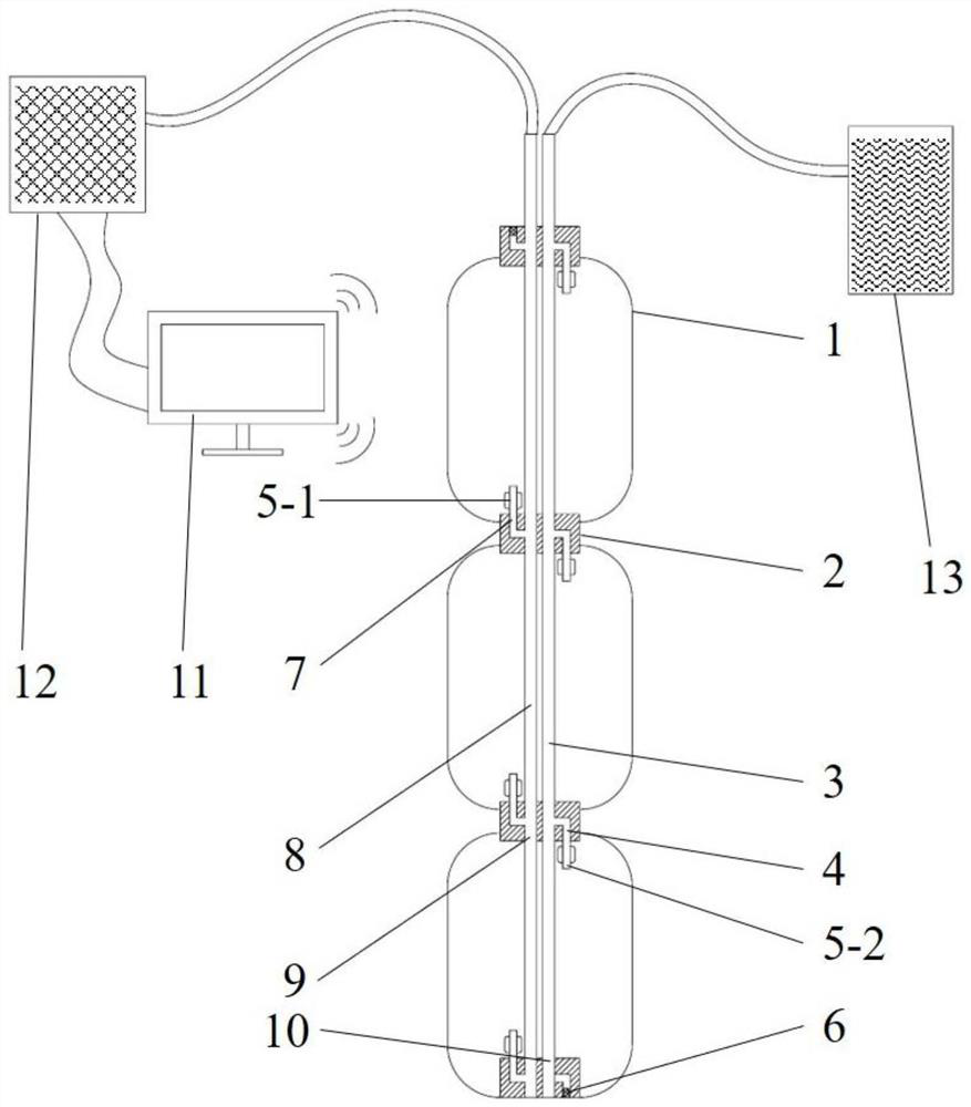
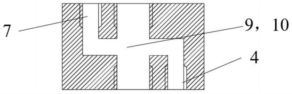
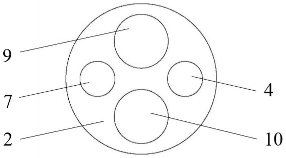
[0016] see Figure 1 ~ Figure 3 , an active and dynamic control method for bladder grouting soil stress, embedding a string of bladders at a setting position, the string of bladders includes a plurality of bladders 1 connected in series, and at both ends of each bladder 1 Each is provided with a joint 2, and a plurality of the bladders 1 are connected in series by parallel grouting pipes 8 and grouting pipes 3, and the grouting pipes 8 and the grouting pipes 3 are connected in sections. Each segment of the pipe joints is connected by a corresponding joint 2. The bottom of the bladder 1 is provided with a grouting pressure solenoid valve 5-1, and the top is provided with a grouting pressure solenoid valve 5-2. The grouting pressure The electr...


PUM


Abstract

The invention discloses a bag type grouting soil stress active dynamic control method. The bag type grouting soil stress active dynamic control method is characterized in that a bag string is embedded in a setting position, a grouting pressure electromagnetic valve and a slurry discharge pressure electromagnetic valve are arranged on a bag, grouting equipment, the grouting pressure electromagnetic valve and the slurry discharge pressure electromagnetic valve are controlled by a computer, in a control system of a computer, opening pressure threshold values in the dynamic adjusting process of the grouting pressure electromagnetic valve and the slurry discharging pressure electromagnetic valve are determined as pressure numerical values of a soil layer where the grouting pressure electromagnetic valve and the slurry discharging pressure electromagnetic valve are buried, then non-condensed slurry is injected, the computer expands the bags to push a soil body to balance soil body stress according to the calculated grouting amount needing to be added to each bag; after the soil body stress is stable, the non-solidified slurry in the bag is replaced with solidified slurry, after the slurry in the bag is solidified, the soil body stress active dynamic control process is finished. The method can be used for protecting the construction safety of the foundation pit and the use safety of adjacent building structures.

Description

technical field [0001] The invention relates to an active control method for foundation pits, in particular to an active and dynamic control method for capsule grouting soil stress. Background technique [0002] With the development of society and economy, large-scale building construction or renovation and expansion projects in urban areas are increasing day by day. Buildings are often accompanied by excavation of foundation pits during the construction process. Because there are many structures (piles, tunnels, etc.) in the urban underground space, if the excavation of the foundation pit is carried out rashly, it is easy to cause adverse effects such as deformation and displacement of the buildings adjacent to the foundation pit, and even endanger the overall stability and safety of the adjacent building structure. Therefore, in order to reduce the impact of foundation pit excavation on surrounding buildings and protect the safety of adjacent buildings, it is necessary to...

Claims


Application Information

Patent Timeline
Patent Type & Authority Applications(China)
IPC IPC(8): E02D3/12E02D15/00E02D17/02
CPCE02D3/12E02D15/00E02D17/02
Inventor 刁钰黄建友郑刚
Owner TIANJIN UNIV
Why Eureka
Try Eureka