Composite vibration hydraulic oscillator and manufacturing method
A hydraulic oscillator and compound vibration technology, applied in the direction of drilling with vibration, can solve the problems of less than 500 hours of service life, uncontrollable frequency, and many rotating parts, which is conducive to the transmission of vibration waves, solves manufacturing problems, The effect of simplifying the structure
- Summary
- Abstract
- Description
- Claims
- Application Information
AI Technical Summary
Problems solved by technology
Method used
Image
Examples
Embodiment 1
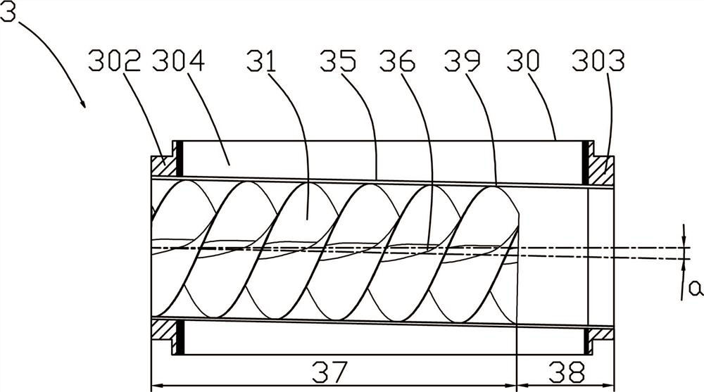
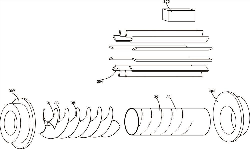
[0047] Such as figure 1 , 3 In ~5, a compound vibrating hydraulic oscillator comprises a pipe body 1, an eccentric turbine 3 is arranged inside the pipe body 1, and a relatively rotatable sliding socket structure is formed between the outer wall of the eccentric turbine 3 and the inner wall of the pipe body 1, A first end face ring 302 and a second end face ring 303 are provided at both ends of the turbine body 30 of the eccentric turbine 3, and the two ends of the inner sleeve 39 are respectively fixedly connected to the first end face ring 302 and the second end face ring 303;
[0048] The hole in the middle of the first end ring 302 , the inner sleeve 39 and the second end ring 303 constitutes an inclined hole 35 penetrating in the axial direction;
[0049] A turbine blade 31 is fixed inside the inner sleeve 39;
[0050] A fixed valve plate 4 is also provided in the pipe body 1, and the fixed valve plate 4 is located downstream of the eccentric turbine 3. The second end f...
Embodiment 2
[0064] Although Embodiment 1 can simplify the structure of the hydraulic oscillator and reduce the cost of the hydraulic oscillator, this solution also has the technical problem that the processing of the eccentric turbine 3 is relatively difficult. On the basis of Example 1, such as figure 1 , 2 Shown in, a kind of method that is used to manufacture above-mentioned composite vibrating hydraulic vibrator comprises the following steps:
[0065] S1. Machining and forming the turbine blade 31; the turbine blade 31 is usually rolled and formed on special rolling roller equipment.
[0066] S2. Weld the turbine blades 31 together through the connecting columns 36 to form a turbine blade assembly; during the welding process, a tool for fixing the turbine blades 31 is required to ensure the connection accuracy between the turbine blades 31 and the connecting columns 36 .
[0067] S3. Finishing the outer contour shape of the turbine blade assembly; the outer contour shape here refers...
PUM
 Abstract
Description
Claims
Application Information
 - R&D Engineer
- R&D Manager
- IP Professional
- Industry Leading Data Capabilities
- Powerful AI technology
- Patent DNA Extraction
Browse by: Latest US Patents, China's latest patents, Technical Efficacy Thesaurus, Application Domain, Technology Topic, Popular Technical Reports.
© 2024 PatSnap. All rights reserved.Legal|Privacy policy|Modern Slavery Act Transparency Statement|Sitemap|About US| Contact US: help@patsnap.com


