
Non-contact rotary potentiometer based on light refraction principle

A non-contact, potentiometer technology, applied in the direction of instruments, optical devices, measuring devices, etc., can solve the problems of reducing detection accuracy, increasing the contact resistance of brushes and resistors, and low life, so as to improve detection accuracy, Improve the anti-vibration ability and improve the service life effect

Active Publication Date: 2021-11-12
CHENGDU HONGMING ELECTRONICS CO LTD
View PDF12 Cites 0 Cited by
  • Summary
  • Abstract
  • Description
  • Claims
  • Application Information

AI Technical Summary

Problems solved by technology

The traditional rotary potentiometer is mainly of the contact type, that is, the rotating shaft drives the brush to touch and slide on the circular resistor to output a changing electrical signal to achieve the purpose of rotation angle detection. The defect of this rotary potentiometer lies in: the brush and the resistor Contact friction is always maintained between the body, so the service life is low, and the precision measurement accuracy is also affected by the contact resistance between the brush and the resistor body, which reduces the detection accuracy to a certain extent, and the brush needs to rely on elasticity to maintain the contact between the resistor body and the brush. In the strong vibration environment, it will increase the contact resistance between the brush and the resistor body and reduce the detection accuracy, so it is not suitable for the strong vibration environment
[0003] In order to overcome the above problems, potentiometers that use magnetic force to achieve angular displacement calibration, such as magnetic steel potentiometers, have the characteristics of non-contact detection, but this type of potentiometer is subject to external magnetic field interference, even if the metal shell is used to achieve the magnetic isolation effect as much as possible, but in It is difficult to avoid magnetic field interference in a strong magnetic environment, thereby reducing the detection accuracy, that is, this type of potentiometer is not suitable for a strong magnetic environment
[0004] In summary, the traditional rotary potentiometers have their own defects, and it is difficult to adapt to the application environment of strong vibration and strong magnetism.

Method used

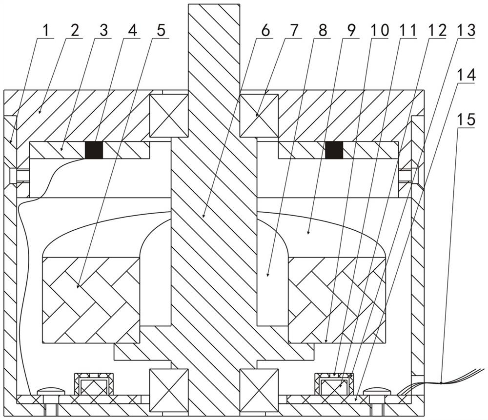
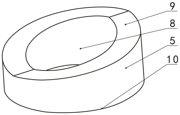

Image

  • Non-contact rotary potentiometer based on light refraction principle
  • Non-contact rotary potentiometer based on light refraction principle
  • Non-contact rotary potentiometer based on light refraction principle

Examples


Embodiment 1

[0033] Such as figure 1 and figure 2 As shown, assume that the light source 4 is located above the refracting lens 5, the photosensitive device 12 is located below the refracting lens 5, the central axis of the refracting lens 5 is vertical, and the lower end surface of the refracting lens 5 is a circular horizontal plane 10. The upper surface of the lens 5 is circular and formed by connecting two symmetrical oblique planes 9 (or arc-shaped surfaces) end to end, that is, using figure 2 In the shown refracting lens 5, the light source 4 is a point light source and is installed on the light-shielding plate 3, the light-shielding plate 3 is installed in the housing, and a light-shielding cover 13 is installed outside the photosensitive device 12, and a light-shielding cover 13 is provided on the upper end of the light-shielding cover 13. Hole 11, in the process of refracting lens 5 rotating 360 °, the outgoing light of light source 4 all can pass through hole 11 of shading cov...

Embodiment 2

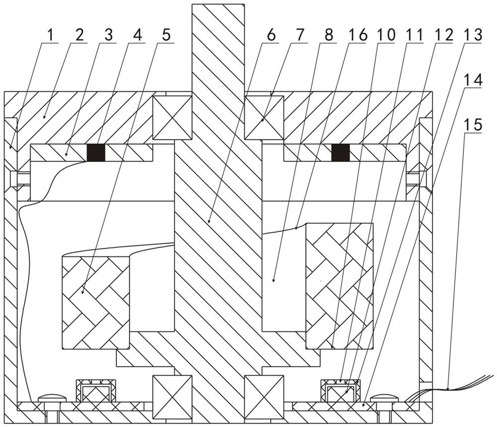
[0036] Such as image 3 and Figure 4 As shown, assume that the light source 4 is located above the refracting lens 5, the photosensitive device 12 is located below the refracting lens 5, the central axis of the refracting lens 5 is vertical, and the lower end surface of the refracting lens 5 is a circular horizontal plane 10. The upper surface of the lens 5 is an integral inclined plane 16 (it can also be an integral arc surface), which gradually rises from one low position to another high position and the low position and high position are located on the same vertical straight line, that is, adopt Such as Figure 4 In the shown refracting lens 5, the light source 4 is a point light source and is installed on the light-shielding plate 3, the light-shielding plate 3 is installed in the housing, and a light-shielding cover 13 is installed outside the photosensitive device 12, and a light-shielding cover 13 is provided on the upper end of the light-shielding cover 13. Hole 11,...

Embodiment 3

[0039] Such as Figure 5 As shown, assume that the light source 4 is located above the refracting lens 5, the photosensitive device 12 is located below the refracting lens 5, the central axis of the refracting lens 5 is vertical, and the lower end surface of the refracting lens 5 is a circular horizontal plane 10. The upper surface of the lens 5 is circular and formed by connecting two symmetrical oblique planes 9 (or arc-shaped surfaces) end to end, that is, using figure 2 In the shown refracting lens 5, the light source 4 is a point light source and is installed on the light-shielding plate 3, the light-shielding plate 3 is installed in the housing, and a light-shielding cover 13 is installed outside the photosensitive device 12, and a light-shielding cover 13 is provided on the upper end of the light-shielding cover 13. Hole 11, in the process of refracting lens 5 rotating 360 °, the outgoing light of light source 4 all can pass through hole 11 of shading cover after being...


PUM


Abstract

The invention discloses a non-contact rotary potentiometer based on a light refraction principle. The non-contact rotary potentiometer based on the light refraction principle comprises a shell, a rotating shaft, a refraction lens, a light source, a photosensitive device and a circuit board; the refraction lens is connected with the rotating shaft and can be driven by the rotating shaft to rotate around the center axis of the refraction lens, and the photosensitive device is correspondingly connected with the circuit board; the light source and the photosensitive device are located on the two axial sides of the refraction lens respectively and meet the following conditions that emergent light of the light source can be projected to the photosensitive end of the photosensitive device after being refracted by the refraction lens, and the positions of the refracted emergent light projected to the photosensitive end of the photosensitive device of the light sourcein the rotation process of the refraction lens are different. The non-contact angular displacement detection function is achieved, the non-contact rotary potentiometer is not affected by contact resistance of a contact component and the like, the detection precision is improved, and the service life of a product is prolonged; the anti-vibration capability can be improved by improving the mechanical connection strength, and the non-contact rotary potentiometer can adapt to a strong vibration environment; the non-contact rotary potentiometer is not influenced by magnetic force, so that the non-contact rotary potentiometer is suitable for strong-magnetic environments.

Description

technical field [0001] The invention relates to a rotary potentiometer, in particular to a non-contact rotary potentiometer based on the principle of light refraction. Background technique [0002] The rotary potentiometer, also known as the angular displacement potentiometer, is a potentiometer used to detect the rotation angle of an object. It is the core component of the angular displacement sensor, and can also be used directly as an angular displacement sensor. The traditional rotary potentiometer is mainly of the contact type, that is, the rotating shaft drives the brush to touch and slide on the circular resistor to output a changing electrical signal to achieve the purpose of rotation angle detection. The defect of this rotary potentiometer lies in: the brush and the resistor Contact friction is always maintained between the body, so the service life is low, and the precision measurement accuracy is also affected by the contact resistance between the brush and the re...

Claims


Application Information

Patent Timeline
IPC IPC(8): G01B11/26
CPCG01B11/26
Inventor 康天骜李鹏飞文亮刘健鲍红军
Owner CHENGDU HONGMING ELECTRONICS CO LTD
Learn More