Ultra-high-cycle fatigue life prediction method and device and storable medium

A technology of fatigue life prediction and life prediction model, which is applied in the direction of measuring devices, using repeated force/pulsation force to test the strength of materials, instruments, etc., can solve the problems that the life prediction accuracy of metal materials cannot be guaranteed, and achieve the effect of improving the prediction accuracy

Pending Publication Date: 2021-11-12
BEIJING INSTITUTE OF TECHNOLOGYGY
View PDF0 Cites 3 Cited by
  • Summary
  • Abstract
  • Description
  • Claims
  • Application Information

AI Technical Summary

Problems solved by technology

On the one hand, this type of method cannot guarantee the life prediction accuracy of metal materials under ultra-high cycle fatigue state; on the other hand, due to the different failure modes of metal materials under ultra-high cycle fatigue state, this type of method cannot target specific failure models for lifetime prediction

Method used


Image

  • Ultra-high-cycle fatigue life prediction method and device and storable medium
  • Ultra-high-cycle fatigue life prediction method and device and storable medium
  • Ultra-high-cycle fatigue life prediction method and device and storable medium

Examples


Embodiment 1

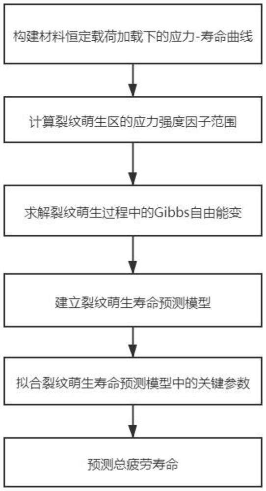
[0088] The embodiment of the present invention discloses a method for predicting the ultra-high cycle fatigue life of metal materials based on the energy method, such as figure 1 shown, including the following steps:

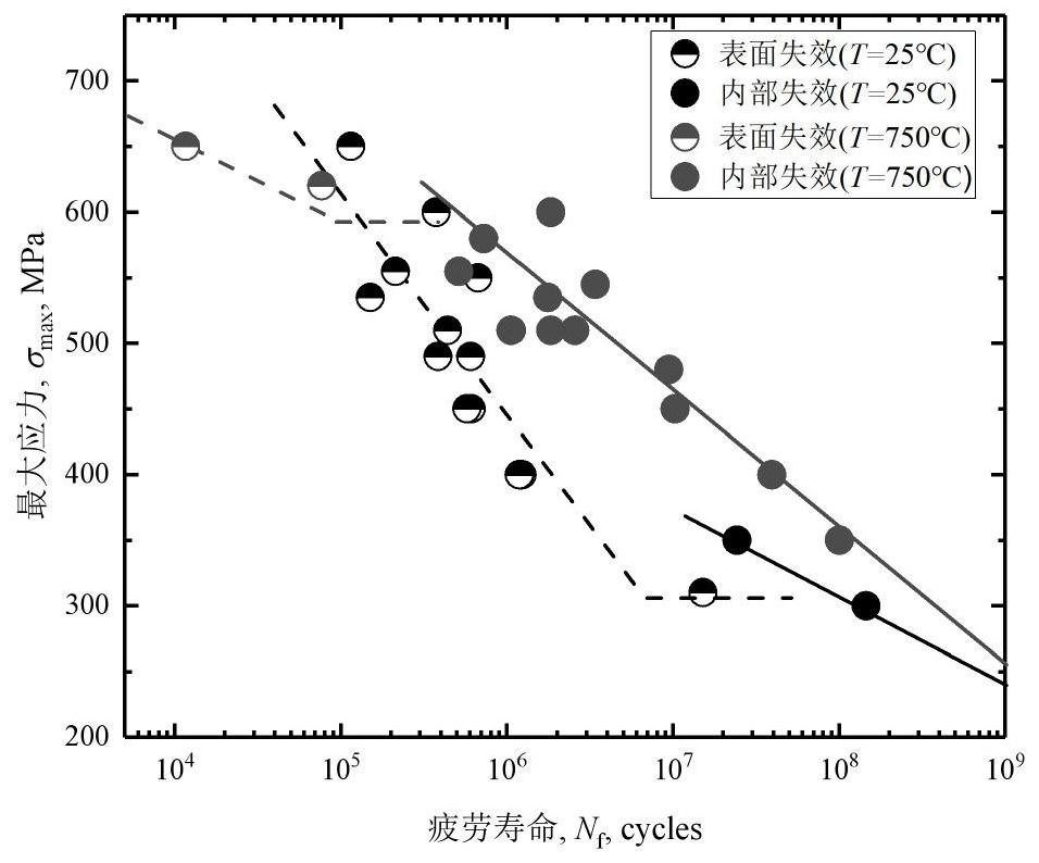
[0089] Conduct fatigue tests on metal materials and construct stress-life curves;

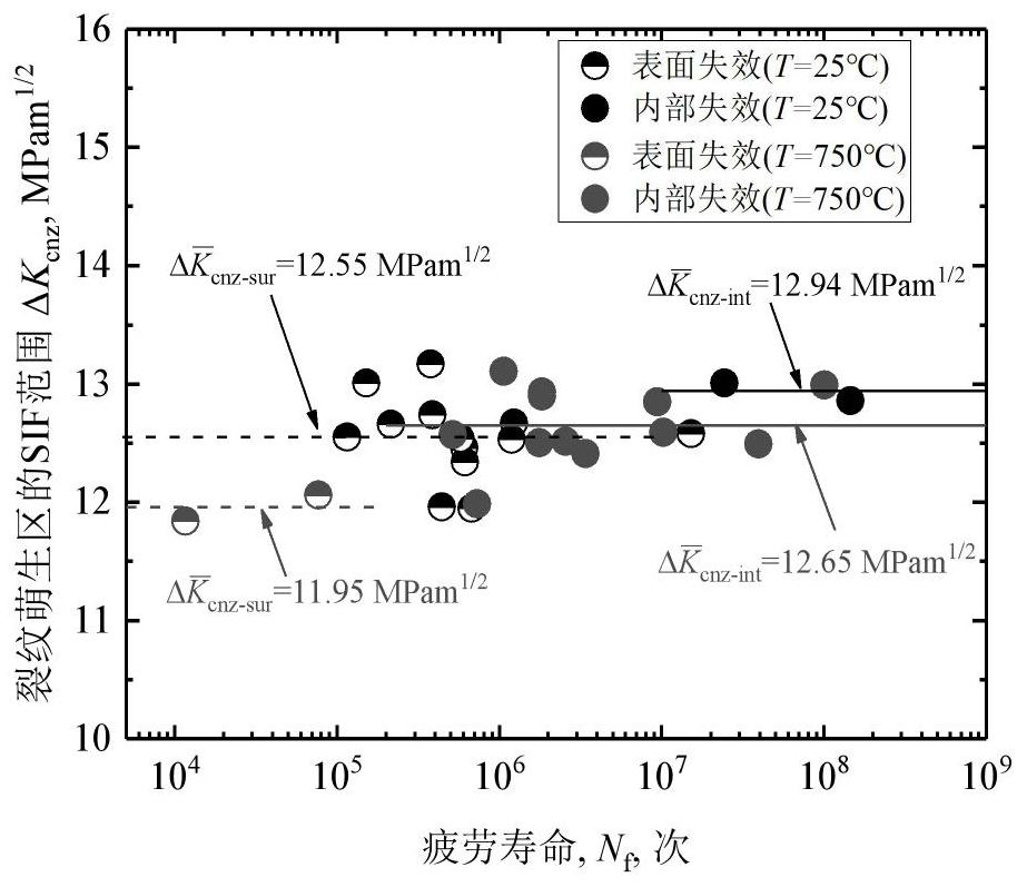
[0090] Measure the characteristic size of the crack initiation zone on the fatigue test fracture, and calculate the stress intensity factor range of the crack initiation zone;

[0091] Based on the fracture mechanics and energy method, the Gibbs free energy change in the process of crack initiation is solved;

[0092] Combined with the strain energy stored in the dislocation dipoles of a single or equivalent slip band, a crack initiation lifetime prediction model is established;

[0093] Combined with the stress-life curve and the characteristic size of the crack initiation zone, the key parameters in the crack initiation life prediction model are fitted;

[0094] The total fa...

Embodiment 2

[0151] The embodiment of the present invention discloses a metal material ultra-high cycle fatigue life prediction device based on the energy method, such as Figure 6 shown, including:

[0152] Obtain a module for constructing the stress-life curve of the material under constant load loading;

[0153] Calculation module, used for calculating the stress intensity factor range of the crack initiation zone;

[0154] The processing module, based on fracture mechanics and energy method, solves the Gibbs free energy change in the process of crack initiation;

[0155] A generating module for establishing a crack initiation life prediction model;

[0156] The training module combines the stress-life curve and the characteristic size of the crack initiation zone to fit the key parameters in the crack initiation life prediction model;

[0157] Prediction module for predicting total fatigue life.

[0158] In one embodiment, a computer storage medium is also provided, on which a comp...


PUM


Abstract

The invention discloses an ultra-high-cycle fatigue life prediction method and device and a storable medium, and relates to the technical field of material life prediction.The method comprises the following steps: conducting a fatigue test on metal materials, and constructing a stress-life curve; measuring a characteristic size of a crack initiation area of a fatigue test fracture, and calculating a stress intensity factor range of the crack initiation area; based on fracture mechanics and an energy method, solving Gibbs free energy change in a crack initiation process; establishing a crack initiation life prediction model by combining strain energy stored in a dislocation dipole of a single slip band or an equivalent slip band; fitting key parameters in the crack initiation life prediction model by combining the stress-life curve and the characteristic size of the crack initiation area; and predicting total fatigue life through the crack initiation life prediction model. For different fatigue failure modes, the invention can combine microstructure characteristics of the metal materials to predict ultra-high-cycle fatigue life of the metal materials based on the energy method, and the prediction precision is improved.

Description

technical field [0001] The invention relates to the technical field of material life prediction, and more specifically relates to a method, device and storage medium for ultra-high cycle fatigue life prediction. Background technique [0002] Railway wheels and tracks, marine structures, bridges, engine components, load-bearing components in the automotive industry, etc. must withstand 10 9 -10 10 a loading cycle. However, most structural material fatigue test studies are usually limited to 10 6 -10 7 test period between periods. According to traditional cognition, when metal material parts bear more than 10 7 After one cycle, it is considered that no fatigue damage will occur, that is, the stress value is called the fatigue limit of the material. However, in recent years, some metal product components with fatigue limit are loaded more than 10 7 The failure will still occur after one cycle. However, with the development of science and technology, the mechanical struc...

Claims


Application Information

Patent Timeline
IPC IPC(8): G06F30/20G01N3/32G06F119/04G06F119/14
CPCG06F30/20G01N3/32G01N2203/0073G06F2119/14G06F2119/04
Inventor 李伟孙锐周思奇
Owner BEIJING INSTITUTE OF TECHNOLOGYGY
Why Eureka
Try Eureka