Conveyor unit for a fuel cell system for conveying and/or controlling a gaseous medium

A fuel cell system and gaseous medium technology, applied in the direction of fuel cells, power system fuel cells, electrical components, etc., can solve the problems of reducing the efficiency of the fuel cell system of the conveying unit, and achieve the effect of improving the effect of the injection pump

Pending Publication Date: 2021-11-12
ROBERT BOSCH GMBH
View PDF9 Cites 0 Cited by
  • Summary
  • Abstract
  • Description
  • Claims
  • Application Information

AI Technical Summary

Problems solved by technology

In addition, eddies and / or flow separations, which are detrimental to the efficiency of the conveyor assembly and / or the fuel cell system, can occur in the conveyor assembly shown in the prior art, especially in the flow region of the outlet bend. This reduces the efficiency of the conveyor unit and / or the overall fuel cell system

Method used


Image

  • Conveyor unit for a fuel cell system for conveying and/or controlling a gaseous medium
  • Conveyor unit for a fuel cell system for conveying and/or controlling a gaseous medium
  • Conveyor unit for a fuel cell system for conveying and/or controlling a gaseous medium

Examples


Embodiment Construction

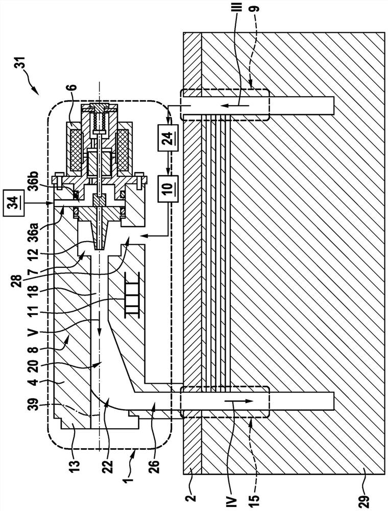
[0025] according to figure 1 The illustration in FIG. 2 shows a schematic sectional view of a fuel cell system 31 with a delivery unit 1 , wherein the delivery unit 1 has a combined valve-injection pump assembly 8 . The combined valve-jet pump assembly 8 here has a metering valve 6 and a jet pump 4 , wherein the metering valve 6 is connected to the jet pump 4 , in particular to the base body 13 of the jet pump 4 , for example by means of a threaded connection.

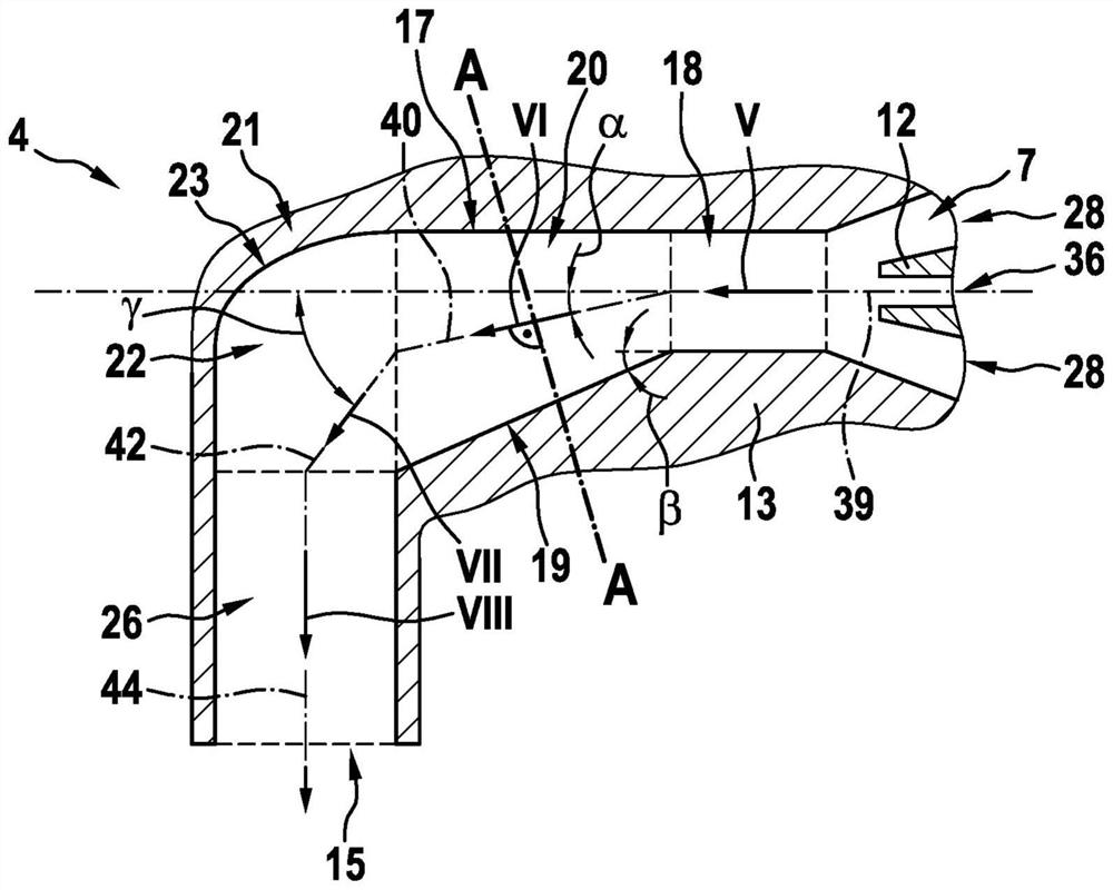
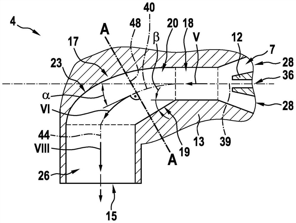
[0026] The jet pump 4 has here in its base body 13 a first inlet 28 , a second inlet 36 a , a suction region 7 , a mixing tube 18 , a diffuser 20 as well as an outlet elbow 22 and / or a connecting piece 26 . The metering valve 6 has a second inlet 36 b and a nozzle 12 . In this case, the metering valve 6 is inserted in particular in the direction of the first longitudinal axis 39 of the mixing tube 18 into an opening in the injection pump 4 , in particular in the base body 13 of the injection pump 4 .

[0027] exist ...


PUM


Abstract

The invention relates to a conveyor unit (1) for a fuel cell system (31) for conveying and / or controlling a gaseous medium, in particular hydrogen, comprising a jet pump (4), which is driven by a propulsion jet of a pressurized gaseous medium, and a metering valve (6), an outlet of the conveyor unit (1) being fluidically connected to an anode inlet (15) of a fuel cell (29). The jet pump (4) has a suction region (7), a mixing tube (18), and a diffuser (20), wherein the diffuser (20) is at least indirectly fluidically connected to the anode inlet (15) of the fuel cell (29), and the gaseous medium flows through the jet pump (4) at least partly in the direction of a first flow direction (V) which runs parallel to a first longitudinal axis (39) of the mixing tube (18). According to the invention, a second longitudinal axis (40) of the diffuser (20) is curved or inclined relative to the first longitudinal axis (39) of the mixing tube (18).

Description

technical field [0001] The invention relates to a conveyor assembly for a fuel cell system for conveying and / or controlling a gaseous medium, in particular hydrogen, which is provided in particular for use in a vehicle with a fuel cell drive. Background technique [0002] In the field of vehicles, besides liquid fuels, gaseous fuels will also become more and more important in the future. Especially in vehicles with a fuel cell drive, the hydrogen flow must be controlled. Here, the gas flow is no longer controlled discontinuously as in the case of liquid fuel injection, but the gaseous medium is taken from at least one tank, in particular a high-pressure tank, and is conducted to the delivery unit via the inflow line of the medium-pressure line system. The delivery unit guides the gas to the fuel cell via the connecting lines of the low-pressure piping system. [0003] From DE 10 2014 221 506 A1 a conveyor unit for conveying a gaseous medium, in particular hydrogen, is know...

Claims


Application Information

Patent Timeline
Patent Type & Authority Applications(China)
IPC IPC(8): F04F5/16F04F5/20F04F5/54H01M8/04089
CPCH01M8/04097F04F5/20F04F5/16F04F5/54Y02E60/50Y02T90/40H01M8/04753H01M2250/20
Inventor A·里希特
Owner ROBERT BOSCH GMBH
Why Eureka
Try Eureka