Millimeter wave antenna direction control method and device, terminal equipment and medium

A millimeter wave antenna and direction control technology, which is applied to antenna supports/installation devices, antennas, antenna parts and other directions, and can solve the problems of long time for terminal equipment to access the base station, a lot of time to rotate the angle, and impact on user experience.

Pending Publication Date: 2021-11-16
QUECTEL WIRELESS SOLUTIONS
View PDF0 Cites 1 Cited by
  • Summary
  • Abstract
  • Description
  • Claims
  • Application Information

AI Technical Summary

Problems solved by technology

[0007] In view of this, the purpose of the embodiments of the present invention is to provide a millimeter-wave antenna direction control method, device, terminal equipment, and medium to solve the problem that it takes a lot of time to determine the rotation angle in the prior art, which causes the time for the terminal equipment to access the base station. Long, the problem that affects the user experience

Method used


Image

  • Millimeter wave antenna direction control method and device, terminal equipment and medium
  • Millimeter wave antenna direction control method and device, terminal equipment and medium
  • Millimeter wave antenna direction control method and device, terminal equipment and medium

Examples


Embodiment Construction

[0039] In order to make the purpose, technical solutions and advantages of the present invention clearer, the technical solutions of the present invention will be clearly and completely described through implementation with reference to the accompanying drawings in the embodiments of the present invention. Obviously, the described embodiments are the embodiment of the present invention. Some, but not all, embodiments. Based on the embodiments of the present invention, all other embodiments obtained by persons of ordinary skill in the art without making creative efforts belong to the protection scope of the present invention.

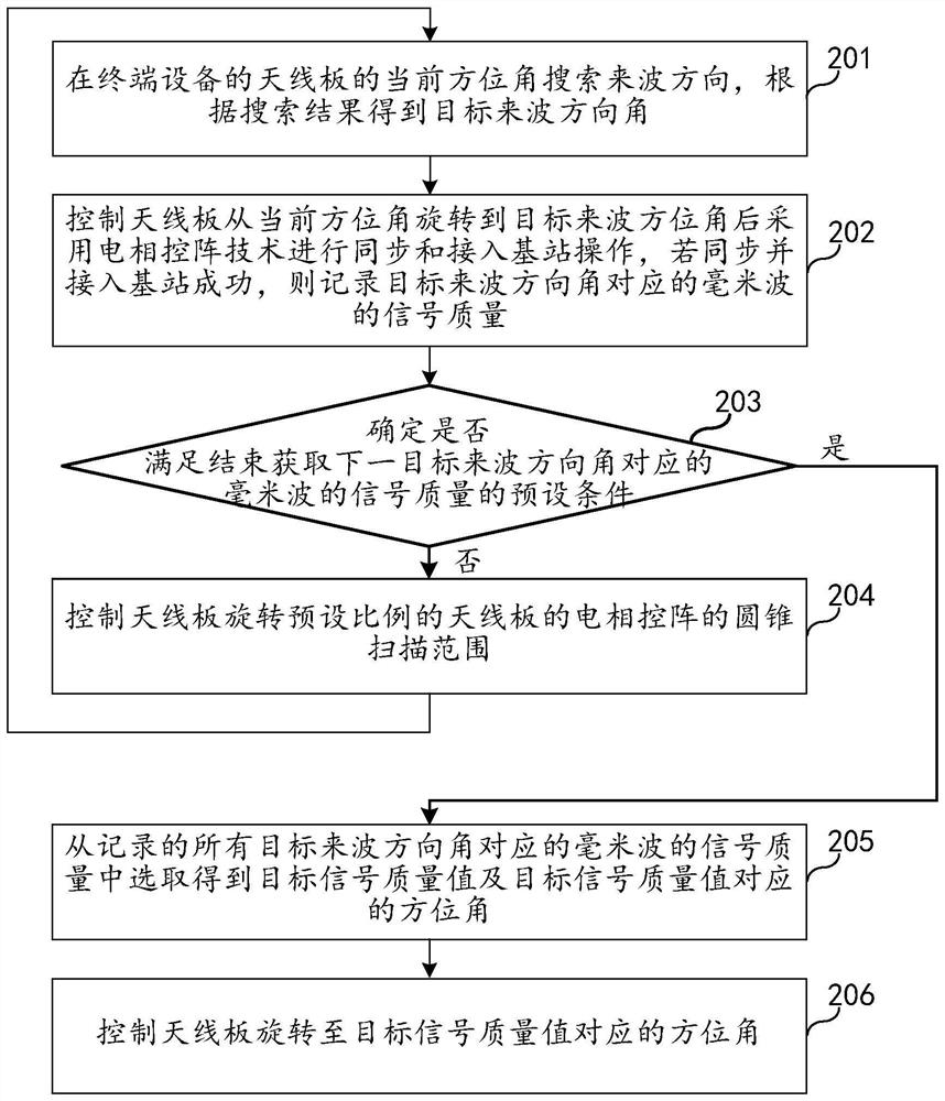
[0040] figure 2It is a flowchart of a method for controlling the direction of a millimeter wave antenna provided by an embodiment of the present invention. The technical solution of this embodiment is applicable to the direction control of the millimeter wave antenna of the terminal device configured with the 5G millimeter wave antenna board. The meth...


PUM


Abstract

The embodiment of the invention relates to the technical field of millimeter wave communication, and discloses a millimeter wave antenna direction control method and device, terminal equipment and a medium. The method comprises the following steps: searching an incoming wave direction at a current azimuth angle of an antenna board to obtain a target incoming wave direction angle; controlling the antenna board to rotate from the current azimuth angle to the target incoming wave azimuth angle, then adopting electric phased array beam scanning to access the base station, and recording the signal quality corresponding to the target incoming wave azimuth angle; if the preset condition for ending the acquisition of the signal quality of the millimeter wave corresponding to the next target incoming wave direction angle is not met, controlling the antenna plate to rotate the conical scanning range of the electric phased array of the antenna plate in a preset proportion, and repeating the steps to obtain the signal quality corresponding to the next target incoming wave direction angle; if the preset condition is met, selecting a target signal quality value and a corresponding azimuth angle from the recorded signal quality corresponding to all the target incoming wave direction angles; and controlling the antenna plate to rotate. Therefore, the time for accessing the base station can be obviously shortened.

Description

technical field [0001] The present invention relates to the technical field of millimeter wave communication, in particular to a method, device, terminal equipment and medium for controlling the direction of a millimeter wave antenna. Background technique [0002] CPE (Customer Premise Equipment, customer premise equipment) is a kind of user terminal equipment for wireless broadband access. CPE is usually used to convert wireless network signals (such as 2G, 3G, 4G, 5G) sent by base stations into WiFi signals. Users only need to insert the SIM card and turn on the power to access the wireless communication network, which can effectively save the laying of wired networks. (such as fiber optic cable, copper wire). Therefore, CPE equipment is widely used in rural areas, cities and towns, hospitals, factories, communities and other occasions where wired networks are not laid. [0003] The fifth generation mobile communication technology (5th generation mobile networks, 5G) is ...

Claims


Application Information

Patent Timeline
Patent Type & Authority Applications(China)
IPC IPC(8): H01Q3/04H01Q1/24H04B17/12H04B17/21H04B17/309
CPCH01Q3/04H01Q1/246H04B17/12H04B17/21H04B17/309
Inventor 袁毅郑雷
Owner QUECTEL WIRELESS SOLUTIONS
Why Eureka
Try Eureka