Welding fixture and application method thereof

A welding fixture and clamping technology, used in welding equipment, electron beam welding equipment, manufacturing tools, etc., can solve the problem of low clamping efficiency of parts, and achieve the goal of improving work efficiency, facilitating repairs, saving costs and equipment time. Effect

Pending Publication Date: 2021-11-19
AECC AVIATION POWER CO LTD
View PDF6 Cites 0 Cited by
  • Summary
  • Abstract
  • Description
  • Claims
  • Application Information

AI Technical Summary

Problems solved by technology

[0003] The purpose of the present invention is to overcome the shortcomings of the above-mentioned prior art, provide a weld

Method used


Image

  • Welding fixture and application method thereof
  • Welding fixture and application method thereof
  • Welding fixture and application method thereof

Examples


Embodiment Construction

[0027] The present invention is described in further detail below in conjunction with accompanying drawing:

[0028] In the description of the present invention, it should be noted that the terms "center", "upper", "lower", "left", "right", "vertical", "horizontal", "inner", "outer" etc. The indicated orientation or positional relationship is based on the orientation or positional relationship shown in the drawings, and is only for the convenience of describing the present invention and simplifying the description, rather than indicating or implying that the referred device or element must have a specific orientation, or in a specific orientation. construction and operation, and therefore cannot be construed as limiting the present invention; the terms "first", "second", and "third" are used for descriptive purposes only, and cannot be construed as indicating or implying relative importance; in addition, unless otherwise Clearly stipulated and limited, the terms "installation"...


PUM


Abstract

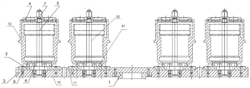
The invention discloses a welding fixture and an application method thereof. The fixture is provided with four machining positions on a flat plate, so that the fixture can clamp four parts, and electron beam welding of four short-shaft parts can be completed at a time; the defect that electron beam welding equipment can only weld one part on one fixture every time is effectively overcome; multiple times of evacuation caused by repeated clamping of the parts are saved, and the cost and the equipment occupation time caused by multiple times of evacuation are saved while the working efficiency is improved; according to the device, four detachable positioning devices are installed on the flat plate, and due to the detachable design mode, a tool can be conveniently repaired, and positioning of the parts can be guaranteed; and the parts are positioned through inner holes and pressed through cover plates, so that positioning of the parts is guaranteed, and installation of the parts is facilitated.

Description

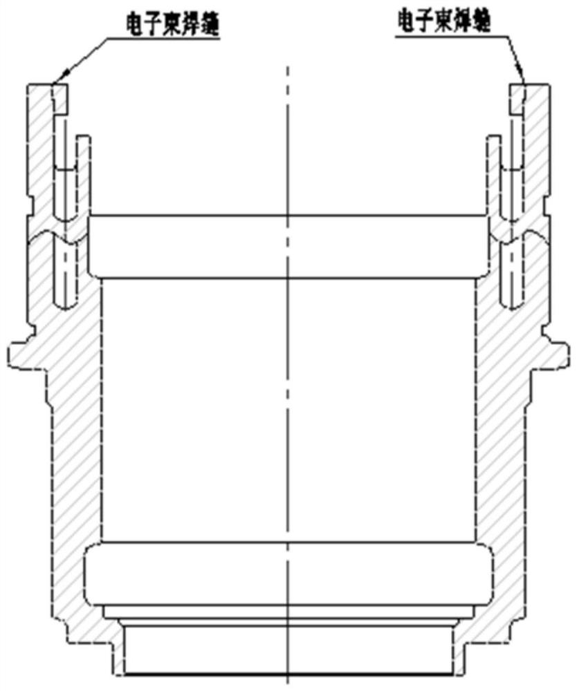
technical field [0001] The invention belongs to the technical field of electron beam welding, and in particular relates to a welding fixture and a using method thereof. Background technique [0002] As a special welding method, electron beam welding has the advantages of good welding accessibility, high joint strength, small welding deformation, large welding thickness, and wide range of weldable materials. It is increasingly used in precision parts in the manufacturing process. Aeroengines have many short shaft parts welded by electron beam, as follows figure 1 As shown, the part is composed of a circumferential weld seam on the end face, the axial height is about 160mm, and the diameter of the weld seam is about 130mm. Only one piece of welding can be completed each time the part is clamped, and the workload is very large and the production efficiency is low. Contents of the invention [0003] The purpose of the present invention is to overcome the above-mentioned shor...

Claims


Application Information

Patent Timeline
IPC IPC(8): B23K15/00B23K15/06
CPCB23K15/0026B23K15/0046B23K15/06
Inventor 王一迪温嵘邹兆安王建涛杨开龙周泉王通
Owner AECC AVIATION POWER CO LTD
Why Eureka
Try Eureka