Insulation and heat insulation wire protection structure for mechanical equipment

A technology of insulation and mechanical equipment, applied in welding equipment, laser welding equipment, metal processing equipment, etc., can solve problems such as wire winding, and achieve the effect of improving work efficiency

Active Publication Date: 2021-11-19
JINTAN HUARONG INSULATING MATERIAL CO LTD
View PDF6 Cites 0 Cited by
  • Summary
  • Abstract
  • Description
  • Claims
  • Application Information

AI Technical Summary

Problems solved by technology

[0003] At present, semi-automatic laser welding machines are widely used, but semi-automatic laser welding machines come with long wires. In order to facilitate the staff to weld steel or other metals, the length and strength of the wires on the semi-automatic welding machine are extremely important. However, at present, the wires that come with the semi-automatic welding machine are all wound on the device, which will bring a certain amount of trouble and difficulty to the user during use and even after use.

Method used


Image

  • Insulation and heat insulation wire protection structure for mechanical equipment
  • Insulation and heat insulation wire protection structure for mechanical equipment
  • Insulation and heat insulation wire protection structure for mechanical equipment

Examples


Embodiment 1

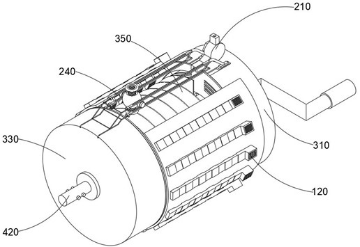
[0048] combine Figure 3-8 As shown, the invention provides an insulating and heat-insulating protective wire structure for mechanical equipment, including a dust reduction mechanism 100, a wire guide mechanism 200, a reinforced rotary mechanism 300, and a torque control mechanism 400. The dust suppression mechanism 100 is installed on the reinforced rotary mechanism 300, The wire guide mechanism 200 is installed outside the reinforced swivel mechanism 300 , and the torque control mechanism 400 is movably connected inside the reinforced swivel mechanism 300 .

[0049] The dust suppression mechanism 100 includes a protective cover 110 and an air-air combination 120, and the air-air combination 120 also includes an exhaust groove 121 and an anion electrode 122, and the wire guide mechanism 200 includes a positioning cover 210, an inner backing ring 220, a nut 230, and a limiting outer frame 240 , collar 250, guide rod 260, spherical warehouse 270, anti-folding pipe 280 and safet...

Embodiment 2

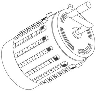
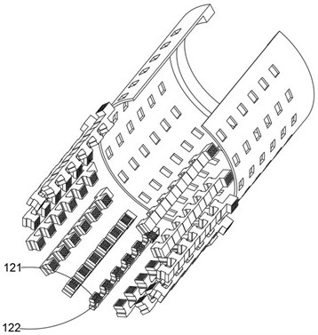
[0052] combine image 3 with 4 As shown, on the basis of Embodiment 1, by using the protective cover 110 to be fixedly installed on the outside of the jacket 330, combined with a plurality of annularly distributed wind and air combinations 120 to adsorb strong pollutants in the device, thereby greatly improving the wire Protected rate, and three pairs of air holes are opened on the inner side of the exhaust groove 121, and the inside of the device is communicated with the external environment by using the exhaust groove 121, thereby facilitating the rapid removal of dust or pollutants. The dust reduction mechanism 100 also includes a protective The air combination 120 inside the outer cover 110, and the air combination 120 is distributed in a ring state along the side wall of the inner cavity of the protective outer cover 110. The air combination 120 also includes an insulating exhaust groove 121 and an anion electrode 122 installed in the inner cavity of the exhaust groove 12...

Embodiment 3

[0054] combine Image 6 As shown, in the above embodiment, by using the positioning cover 210 to guide the direction of the wire, the safety during the winding of the wire can be ensured, and two anti-folding tubes 280 are respectively installed at the top and bottom of the inner cavity of the spherical warehouse 270 , use the anti-folding tube 280 to protect the wires, thereby reducing the wear and tear during the stretching or gathering of the outer insulating layer of the wires, and set an inwardly recessed circular ring notch in the middle of the outer side of the inner backing ring 220, and use the inner backing ring 220 to The outer insulating layer of the wire increases the frictional resistance, so that the stability of the wire during stretching and winding can be controlled. When the wire passes through the inner cavity of the anti-bending tube 280, the two silicone rings can greatly reduce the impact of the outer insulating layer of the wire. For the wear and tear o...


PUM


Abstract

The invention discloses an insulation and heat insulation wire protection structure for mechanical equipment. The structure comprises a dust falling mechanism, a wire guide mechanism, a reinforced rotary mechanism and a torsion control mechanism, wherein the dust falling mechanism comprises a protective cover for protecting a wound wire; the wire guide mechanism comprises a limiting outer frame, a shaft ring arranged in the middle of the limiting outer frame, a guide rod connected to the interior of the shaft ring and a safety frame installed outside the limiting outer frame; and the reinforced rotary mechanism comprises an outer sleeve used for conducting gas transmission on the wound wire and a wire bunching part located at the inner side of the outer sleeve. A stabilizing gasket is arranged in the inner cavity of the wire bunching part, meanwhile, a torsional spring is installed at the inner side of the stabilizing gasket, a rocker outside a transmission rod is rotated to drive an inner shaft and increase torsion for the torsional spring, and the inner shaft and the transmission rod are pulled and pushed to control conveying and automatic recycling of wires at the inner side of the wire bunching part. Therefore, the working efficiency of users can be greatly improved.

Description

technical field [0001] The invention relates to the technical field of mechanical equipment cable protection, in particular to an insulation and heat insulation protection wire structure for mechanical equipment. Background technique [0002] With the rapid development of the social manufacturing industry, people began to use a large number of mechanical equipment to replace manual welding of difficult steel frame structures, especially the use of laser welding machines today. According to different application fields, in manufacturing, powder In the fields of metallurgy, automobile industry, electronics industry and biomedicine, laser welding machines are also divided into semi-automatic and fully automatic. [0003] At present, semi-automatic laser welding machines are widely used, but semi-automatic laser welding machines come with long wires. In order to facilitate the staff to weld steel or other metals, the length and strength of the wires on the semi-automatic welding...

Claims


Application Information

Patent Timeline
Patent Type & Authority Applications(China)
IPC IPC(8): B23K26/70H02G11/02
Inventor 陆帮荣
Owner JINTAN HUARONG INSULATING MATERIAL CO LTD
Why Eureka
Try Eureka