Clamping tool for crankshaft repairing and application method thereof

A technology for clamping tooling and crankshaft, applied in the field of clamping tooling for crankshaft repair, can solve the problem that the device cannot be clamped, and achieve the effects of easy discharge, easy shock absorption, and increased clamping degree

Pending Publication Date: 2021-11-19
客镭定科技南通有限公司
View PDF5 Cites 1 Cited by
  • Summary
  • Abstract
  • Description
  • Claims
  • Application Information

AI Technical Summary

Problems solved by technology

[0004] The invention provides a clamping tool for crankshaft repair and its use method. By using a hydraulic rod to drive the top plate to move, it facilitates the rapid clamping of the device, increases the clamping degree of the device, and avoids the use of a manual clamping device, which causes the device to be unable to clamp The problem

Method used


Image

  • Clamping tool for crankshaft repairing and application method thereof
  • Clamping tool for crankshaft repairing and application method thereof
  • Clamping tool for crankshaft repairing and application method thereof

Examples


Embodiment 1

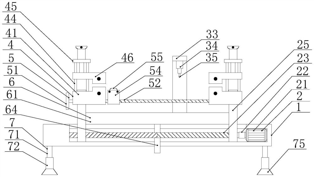
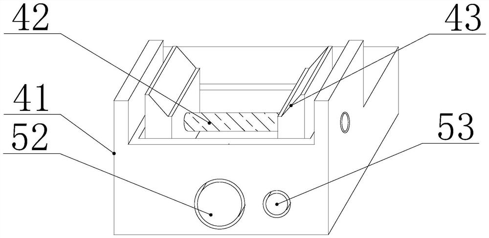
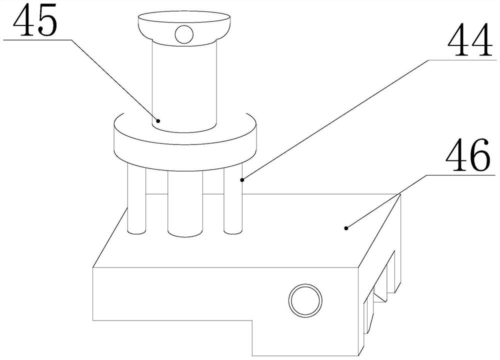
[0034] Such as Figure 1-3 As shown, the present invention is a clamping tool for crankshaft repair and its use method, including a workbench 1, a length adjustment mechanism 2 is provided inside the workbench 1, which is convenient for adjusting and adapting to crankshafts of different sizes, and the workbench 1 is close to the length adjustment mechanism 2 One end is provided with a moving mechanism 3, which is convenient for the movement of the spraying end. The top end of the length adjustment mechanism 2 is provided with a clamping mechanism 4, which is convenient for clamping and fixing the crankshaft. In addition, the top of the workbench 1 is provided with a waste discharge mechanism 6, which is convenient for the discharge of waste materials. The bottom of the workbench 1 is provided with a shock absorbing mechanism 7, which is convenient for reducing the vibration of the device. The length adjustment mechanism 2 includes a movable support plate 25, and the clamping me...

Embodiment 2

[0038] see Figure 5 , further improvements have been made on the basis of Example 1:

[0039] In order to adapt to crankshafts of different lengths, two mutually symmetrical movable support plates 25 are threaded through a first two-way threaded rod 23 and a second two-way threaded rod 24 in the device.

[0040] In this embodiment, the length adjustment mechanism 2 includes a first motor 21, the first motor 21 is fixedly connected to the inner cavity of the workbench 1, and the output end of the first motor 21 is fixedly connected with a first two-way threaded rod 23, the first two-way threaded rod 23 Both ends are symmetrically threaded to be connected with a movable support plate 25, the output end of the first motor 21 is covered with a belt 22, the first motor 21 is movably connected with a second two-way threaded rod 24 through the belt 22, and the two movable support plates 25 are threaded on the second On the two-way threaded rod 24, the belt 22 is driven by the first m...

Embodiment 3

[0044] see figure 1 , further improvements have been made on the basis of Example 1:

[0045] In order to free hands, reduce labor force, and increase work efficiency, by using the scraping mechanism 5, the scraping of the device is facilitated, and manual scraping is avoided. When unskilled, it is necessary to stop the machine for scraping, resulting in relatively low efficiency.

[0046] In this embodiment, the scraping mechanism 5 includes a second one-way threaded rod 52 and a limit rod 53, both of which pass through two bottom plates 41, and the second one-way threaded rod 52 and the limit rod 53 pass through a moving block 54, the handle 51 fixedly connected to one end of the second one-way threaded rod 52, and the handle 51 drives the second one-way threaded rod 52 to rotate, so that the moving block 54 can move along the limit Rod 53 moves so that scraper 55 bolted on top of moving block 54 scrapes excess debris off the crankshaft.


PUM


Abstract

The invention relates to a clamping tool for crankshaft repairing and an application method thereof. The clamping tool for crankshaft repairing comprises a workbench, wherein a length adjusting mechanism is arranged in the workbench; a welding moving mechanism is arranged at the end, close to the length adjusting mechanism, of the workbench; clamping mechanisms are arranged at one end of the top of the length adjusting mechanism; a scraping mechanism is arranged between the clamping mechanisms; a waste discharging mechanism is arranged at the top of the workbench; a damping mechanism is arranged at the bottom of the workbench; and the length adjusting mechanism comprises a movable supporting plate. The clamping tool for crankshaft repairing provided by the invention achieves the beneficial effects that hydraulic rods are used for driving top plates to move, so that rapid clamping of the device is facilitated; a first motor is used for driving two bidirectional threaded rods to rotate, so that crankshafts with different sizes can be conveniently clamped and fixed; a moving block is driven by a handle to move to a proper position, so that redundant residues on the crankshaft are conveniently scraped by a scraper, and influence on use of the device is prevented; a vibration motor drives an inclined plate to vibrate, so that waste is conveniently discharged; and screw rods rotate to extrude and penetrate through springs, so that the displacement distances of movable rods are reduced, and damping is facilitated.

Description

technical field [0001] The invention relates to the technical field of crankshaft repair, in particular to a clamping tool for crankshaft repair and a use method thereof. Background technique [0002] The crankshaft is an important part of the engine. Due to its continuous reciprocating motion, it will generate a lot of wear. This wear is uneven and needs to be repaired by using a spray gun. [0003] The existing clamping tool for repairing the crankshaft is generally fixed by a three-jaw chuck, and the crankshaft needs to be clamped manually, which is very troublesome and the efficiency is relatively low. The existing device lacks a length adjustment structure and cannot be used for different lengths The crankshaft is clamped. In the existing structure, the residue sprayed by the spray gun on the crankshaft needs to be manually cleaned to prevent the repair of the crankshaft from being affected. However, this method is relatively inefficient and the labor cost is relatively...

Claims


Application Information

Patent Timeline
Patent Type & Authority Applications(China)
IPC IPC(8): B23Q3/08B23Q11/00B08B1/00
CPCB23Q3/082B23Q11/0042B23Q11/0032B08B1/005
Inventor 蔡淳佑
Owner 客镭定科技南通有限公司
Why Eureka
Try Eureka