High-precision environment-friendly machining equipment for hollow abrasive material and abrasive belt

A kind of processing equipment, high-precision technology, applied in the direction of metal processing equipment, grinding/polishing equipment, abrasives, etc., to achieve the effect of increasing linkage and increasing practicability

Pending Publication Date: 2021-11-19
盐城市锐克斯研磨科技有限公司
View PDF0 Cites 0 Cited by
  • Summary
  • Abstract
  • Description
  • Claims
  • Application Information

AI Technical Summary

Problems solved by technology

[0005] The purpose of the present invention is to provide a high-precision environmental protection processing equipment for hollow abrasive abrasive belts. The uniform glue coating mechanism can effectively avoid the abrasive material being unable to be completely bonded to the outside due to uneven glue coating on the outside of the base material of the abrasive belt body. to solve the problems raised in the above-mentioned background technology

Method used


Image

  • High-precision environment-friendly machining equipment for hollow abrasive material and abrasive belt
  • High-precision environment-friendly machining equipment for hollow abrasive material and abrasive belt
  • High-precision environment-friendly machining equipment for hollow abrasive material and abrasive belt

Examples


Embodiment 1

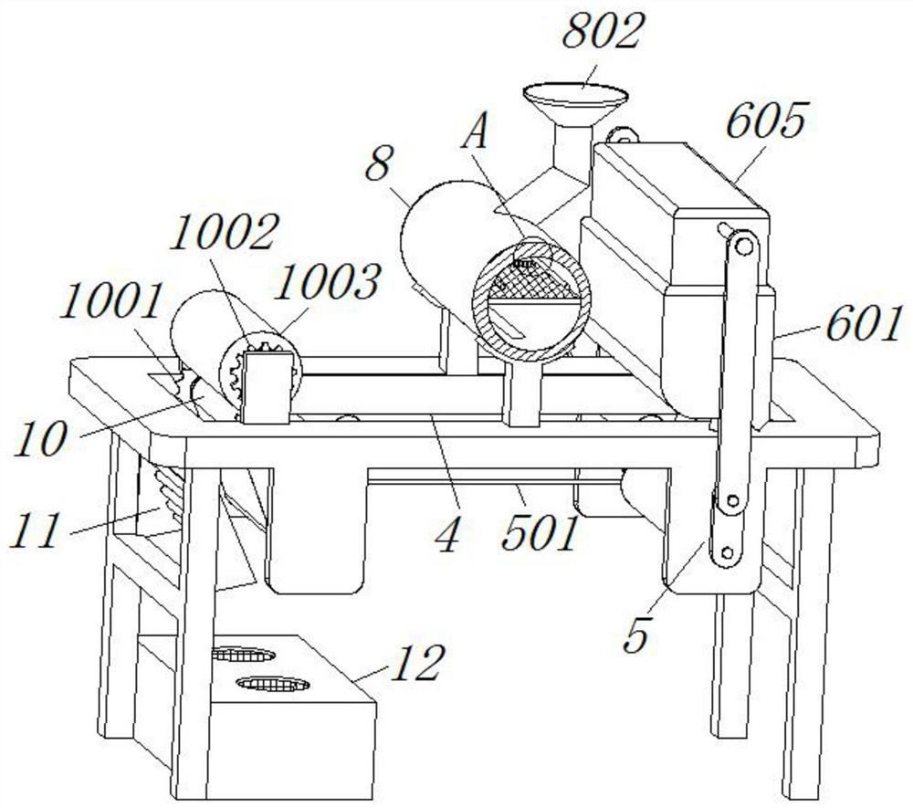
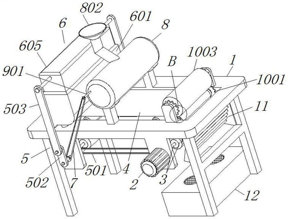
[0034] see Figure 2-3 and Figure 7 , the extrusion mechanism 5 includes a first sprocket mechanism 501 and a rotating plate 502 installed on the outside of the two main shaft revolving wheels 3, and the rotating plate 502 is connected with a connecting plate 503 through a shaft bearing, and the length of the rotating plate 502 is the connecting plate 503 A quarter of the length dimension, the uniform gluing mechanism 6 includes a material storage frame 601 fixed on the left side above the workbench 1, and the inside bottom of the workbench 1 is fixed with a gasket 602 through a rod, and the bottom of the gasket 602 is provided with a coating Soft rubber 603, one-way air valves 604 are installed on the left and right sides above the material storage frame 601, and the inner side of the material storage frame 601 is also engaged with an extrusion piston 605, and the soft rubber 603 is smeared in an opening shape, and the upper side of the extrusion piston 605 The front and re...

Embodiment 2

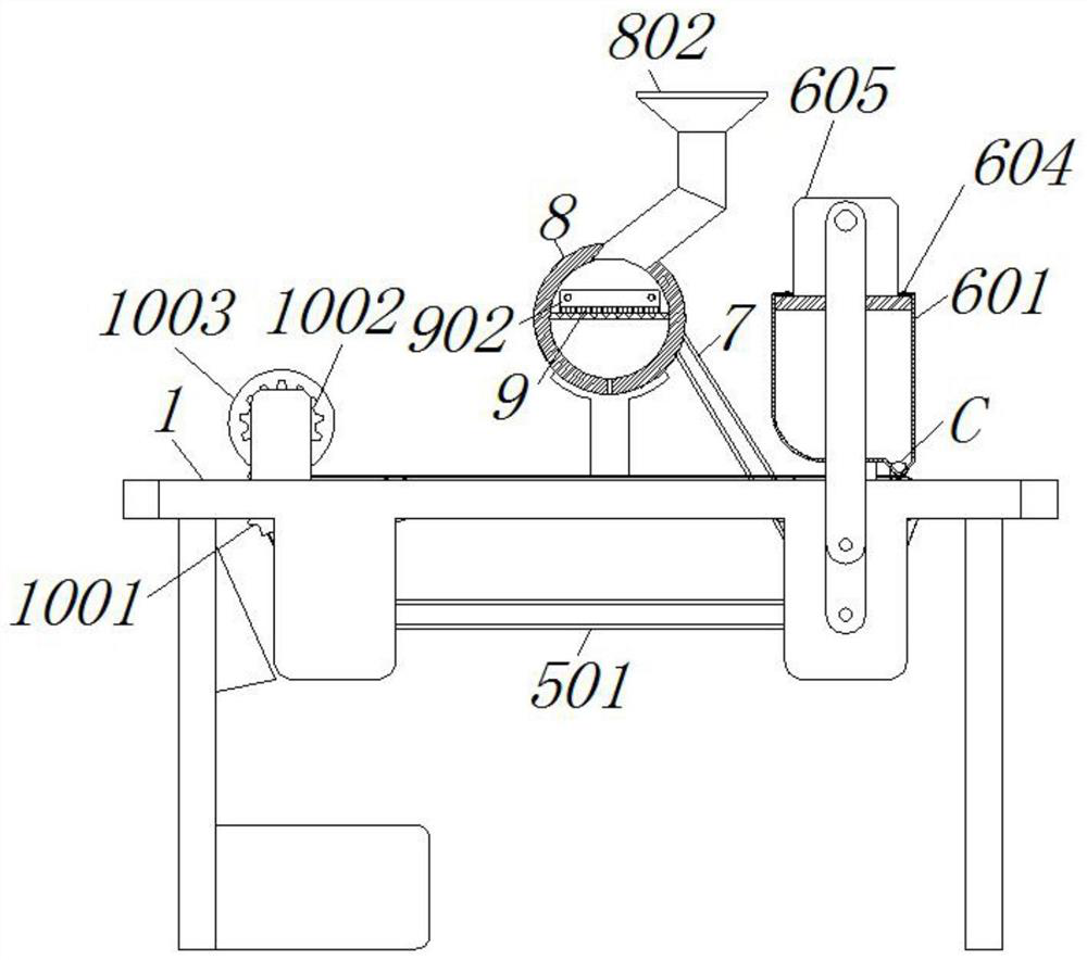
[0036] see Figure 3-5 , and the difference from Example 1 is: the inner side of the abrasive cylinder 8 is welded with a mesh plate 801, and the top of the abrasive cylinder 8 is provided with a feed pipe 802, the feed pipe 802 is inclined, and the uniform spreading mechanism 9 includes a bearing connected to the abrasive material. The reciprocating screw rod 901 on the inner side of the cylinder 8, and the outer side of the reciprocating screw rod 901 is threadedly connected with a slider 902, and the polished rod 903 is connected to the left side of the original reciprocating screw rod 901, and the bottom of the slider 902 is welded with a dispersing rod 904. The dispersing rod 904 Both are in contact with the screen plate 801, and the dispersing roller 904 forms a front and rear sliding structure through the slider 902 and the abrasive cylinder 8. Firstly, an appropriate amount of abrasive is introduced into the inner side of the abrasive cylinder 8 through the feeding tube...

Embodiment 3

[0038] see figure 2 and Figure 6 The difference from Embodiment 1 is that the pressing mechanism 10 includes a lower gear 1001 fixed on the right side of the main shaft winding wheel 3, and an upper gear 1002 meshes above the lower gear 1001, and a rubber rod 1003 is fixed on the upper gear 1002 through the shaft , when the main shaft on the right side rotates around the wheel 3, it can also drive the lower gears 1001 on the front and rear sides to rotate, and drive the upper gear 1002 meshed above it to rotate in the opposite direction, and the upper gear 1002 rotates to cooperate with the rotating shaft to drive the rubber rod 1003 Rotate, because the outer side of the bottom of the rubber rod 1003 is in contact with the outer side of the abrasive belt body 4 after the abrasive is spread, so the abrasive material bonded to the outer side of the abrasive belt body 4 can be compacted by the rotation of the rubber rod 1003.

[0039] The working principle of the present inven...


PUM


Abstract

The invention discloses high-precision environment-friendly machining equipment for a hollow abrasive material and an abrasive belt. The equipment comprises a workbench, a servo motor is installed on the right side of the front of the workbench, a uniform gluing mechanism capable of uniformly applying a binder to the outer side of a base layer material of an abrasive belt body is arranged on the inner side of an extrusion mechanism, a second chain wheel mechanism is in key connection with the left side of a main shaft winding wheel, and a pressing mechanism capable of compacting and stabilizing the abrasive material spread to the adhesive belt body is connected to the right side of the upper part of the workbench. The uniform gluing mechanism cooperates with the ascending and descending of the extrusion mechanism, so that an extrusion piston can be effectively driven to uniformly extrude out the binder on the inner side of a storage frame by applying flexible glue through cooperation with gaskets and one-way air valves, the outer side of the base layer material of the abrasive belt body is uniformly applied, and meanwhile the problem that the abrasive material cannot be completely bonded to the outer side of the base layer material of the abrasive belt body due to non-uniform gluing on the outer side of the base layer material of the abrasive belt body can be effectively solved.

Description

technical field [0001] The invention relates to the field of abrasive belts, in particular to high-precision and environmentally friendly processing equipment for hollow abrasive abrasive belts. Background technique [0002] The hollow abrasive abrasive belt is usually used in the field of mechanical processing. It is mainly a belt-shaped tool that can be used for grinding and polishing by using a binder to bond abrasives to flexible materials such as paper and cloth. A main form of coated abrasives, its basic composition is: base material, abrasive and binder, collectively known as the three elements of the abrasive belt, and the hollow abrasive belt still has various defects in the process of processing, just for example: [0003] It is not convenient to evenly spread the adhesive on the outer surface of the base layer of the abrasive belt, and at the same time it is not cheap to evenly spread the abrasive on the outer surface of the coated abrasive belt base layer, resul...

Claims


Application Information

Patent Timeline
Patent Type & Authority Applications(China)
IPC IPC(8): B24D11/00B24D18/00
CPCB24D11/001B24D18/0072
Inventor 王志成
Owner 盐城市锐克斯研磨科技有限公司
Why Eureka
Try Eureka