
A manipulator for carrying heavy objects in a radiation environment

A radiation environment and manipulator technology, applied in the field of manipulators, can solve the problems that the manipulator cannot carry heavy objects and the manipulator cannot respond to changes, and achieves the effects of stable clamping, optimized clamping capacity and convenient operation.

Active Publication Date: 2022-07-22
JIANGSU IRON ANCHOR GLASS LTD BY SHARE LTD
View PDF8 Cites 0 Cited by
  • Summary
  • Abstract
  • Description
  • Claims
  • Application Information

AI Technical Summary

Problems solved by technology

[0005] In a space with radiation, manipulators are often used to carry radiation objects, but existing manipulators cannot carry heavy objects such as barrels or cans, and when the above two materials cannot be distributed and transported, the manipulator cannot respond to changes

Method used


Image

  • A manipulator for carrying heavy objects in a radiation environment
  • A manipulator for carrying heavy objects in a radiation environment
  • A manipulator for carrying heavy objects in a radiation environment

Examples


Embodiment 1

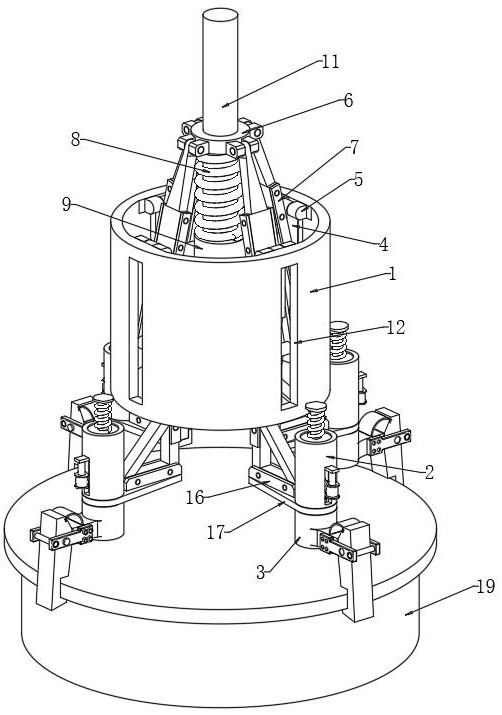
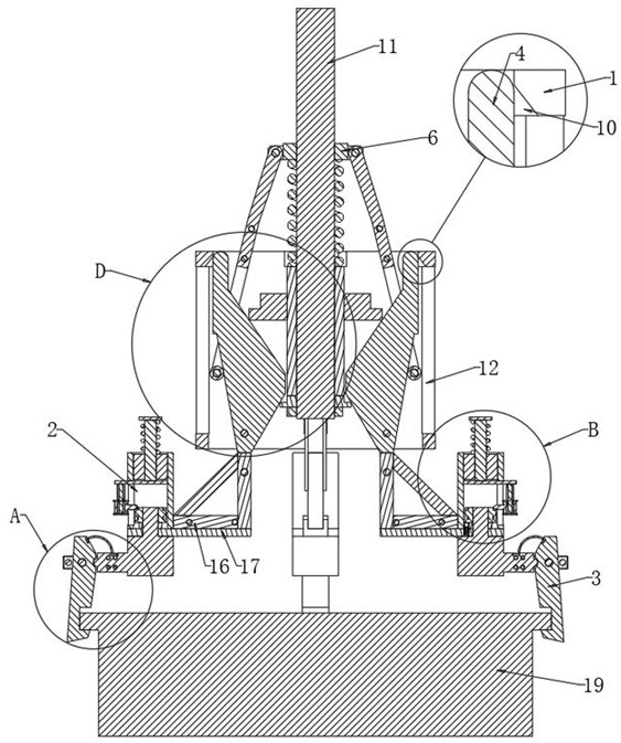
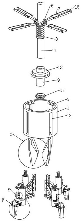
[0038] see Figure 1-11 , a manipulator for carrying heavy objects in a radiation environment, including a fixed sleeve 1, a drive shaft 11 is arranged in the middle of the inner wall of the fixed sleeve 1, and a plurality of hinge joints 5 are distributed in an array on the top of the inner wall of the fixed sleeve 1. A limit plate 4 is rotated and hinged between the hinge joints 5, and a plurality of limit plates 4 can improve the stability of clamping round and square objects. The outer side of the fixing sleeve 1 is fixedly connected with a ring 6, and the ring The outer side of 6 is hinged with a plurality of connecting plates 7, one end of the connecting plate 7 is rotatably connected with a cylindrical rolling ring 18, and the connecting plate 7 is adapted to the position of the limit plate 4, and the cylindrical rolling ring 18 is located between the limit plate 4 and the limit plate 4. Between the fixing sleeves 1, one side of the limit plate 4 is supported by the cyl...

Embodiment 2

[0048] see Figure 10-11 The difference between this embodiment and the first embodiment is that the opening of the clamping groove 305 on the clamping device 3 is far away from the middle of the fixing sleeve 1 .

[0049] Compared with the fact that the opening of the clamping groove 305 on the clamping device 3 is close to the middle of the fixing sleeve 1 , the embodiment 2 can clamp the hollow tube-like article without reducing the clamping stability.

[0050] In use: by lifting the drive shaft 11 up, the circular ring 6 is driven to move down, and then the cylindrical rolling ring 18 is moved down to achieve the limit and detachment of the limiting plate 4, and then the sliding sleeve 9 is pressed down by the circular ring 6 , so that the pressure ring 13 squeezes the limit plate 4, so that the limit plate 4 swings around the hinge joint 5, so as to increase the interval between the connecting plates 7, until the clamping device 3 and the outer wall of the barrel-shaped w...


PUM


Abstract

The invention discloses a manipulator for carrying heavy objects in a radiation environment, belonging to the field of automation. A limit plate is rotatably hinged between the hinge joints, a circular ring is fixedly connected to the outer side of the fixed sleeve, a plurality of connecting plates are hinged on the outer side of the circular ring, and one end of the connecting plate is rotatably connected with a cylindrical rolling ring, and The connecting plate is adapted to the position of the limit plate, the cylindrical rolling ring is located between the limit plate and the fixed sleeve, one side of the annular ring is slidably sleeved with a spring and a sliding sleeve, and one end of the annular ring is connected to the support ring For fixed connection, the spring and the sliding sleeve are arranged between the circular ring and the fixed sleeve, and the adjacent ends of the spring, the sliding sleeve and the support ring are closely fitted. It can be realized that the manipulator can be adjusted according to the different objects to be carried, and can carry heavy objects.

Description

technical field [0001] The invention relates to the field of automation, and more particularly, to a manipulator for carrying heavy objects in a radiation environment. Background technique [0002] A manipulator is an automatic operation device that can imitate certain action functions of human hands and arms to grab, carry objects or operate tools according to a fixed program. The feature is that it can be programmed to complete a variety of expected operations, and the structure and performance have the advantages of both human and robotic machines. [0003] The manipulator is the earliest industrial robot and the earliest modern robot. It can replace the heavy labor of humans to realize the mechanization and automation of production, and can operate in harmful environments to protect personal safety. Therefore, it is widely used in machinery manufacturing, metallurgy, Electronics, light industry and atomic energy sectors. [0004] Machines fail because radiation excites...

Claims


Application Information

Patent Timeline
Patent Type & Authority Patents(China)
IPC IPC(8): B25J9/00B25J9/10
CPCB25J9/0009B25J9/10
Inventor 吴贲华贾学军张志勇贲海峰
Owner JIANGSU IRON ANCHOR GLASS LTD BY SHARE LTD
Learn More