Hydraulic engineering safety gate capable of being self-locked

A technology for water conservancy projects and safety gates, which is applied in water conservancy projects, sea area engineering, construction, etc., can solve the problems of adverse effects on the stability of the screw gate system, low reliability and automation, and affect the response speed of gate opening and closing, etc., to achieve Avoid force, stable positioning, fast response effect

Pending Publication Date: 2021-11-19
战祥刚
View PDF5 Cites 0 Cited by
  • Summary
  • Abstract
  • Description
  • Claims
  • Application Information

AI Technical Summary

Problems solved by technology

[0006] The purpose of the present invention is to provide a self-locking water conservancy safety gate to solve the problem that the gate is normally in the lifting position in the above-mentioned background technology, and the stress on the screw and the stability of the entire gate system have adverse effects, which are easy to cause Accidents: manual locking, its reliability and automation are low, it cannot be locked at any time, the operation method is complicated, and the lock is simply supported by a bracket, which lacks stability and seriously affects the opening and closing response speed of the gate.

Method used


Image

  • Hydraulic engineering safety gate capable of being self-locked
  • Hydraulic engineering safety gate capable of being self-locked
  • Hydraulic engineering safety gate capable of being self-locked

Examples


Embodiment Construction

[0030] The following will clearly and completely describe the technical solutions in the embodiments of the present invention with reference to the accompanying drawings in the embodiments of the present invention. Obviously, the described embodiments are only some, not all, embodiments of the present invention. Based on the embodiments of the present invention, all other embodiments obtained by persons of ordinary skill in the art without creative efforts fall within the protection scope of the present invention.

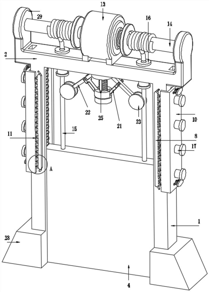
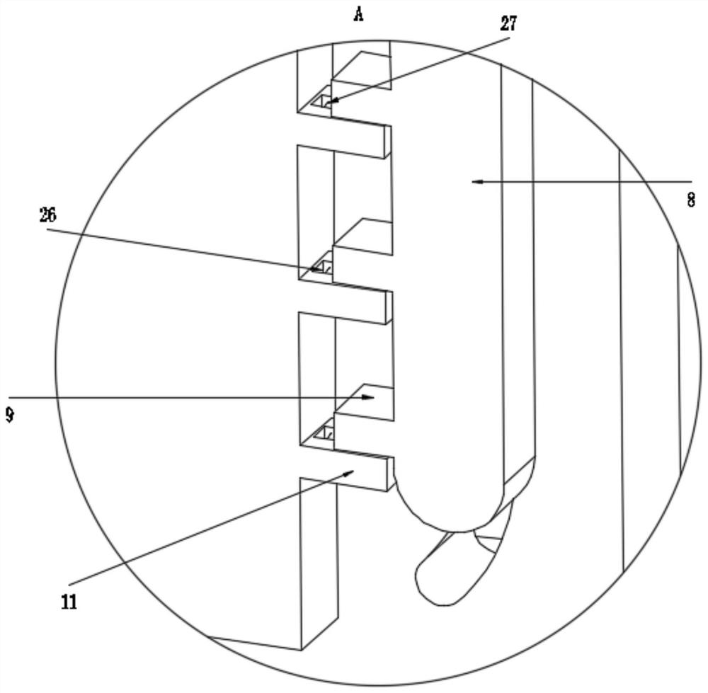
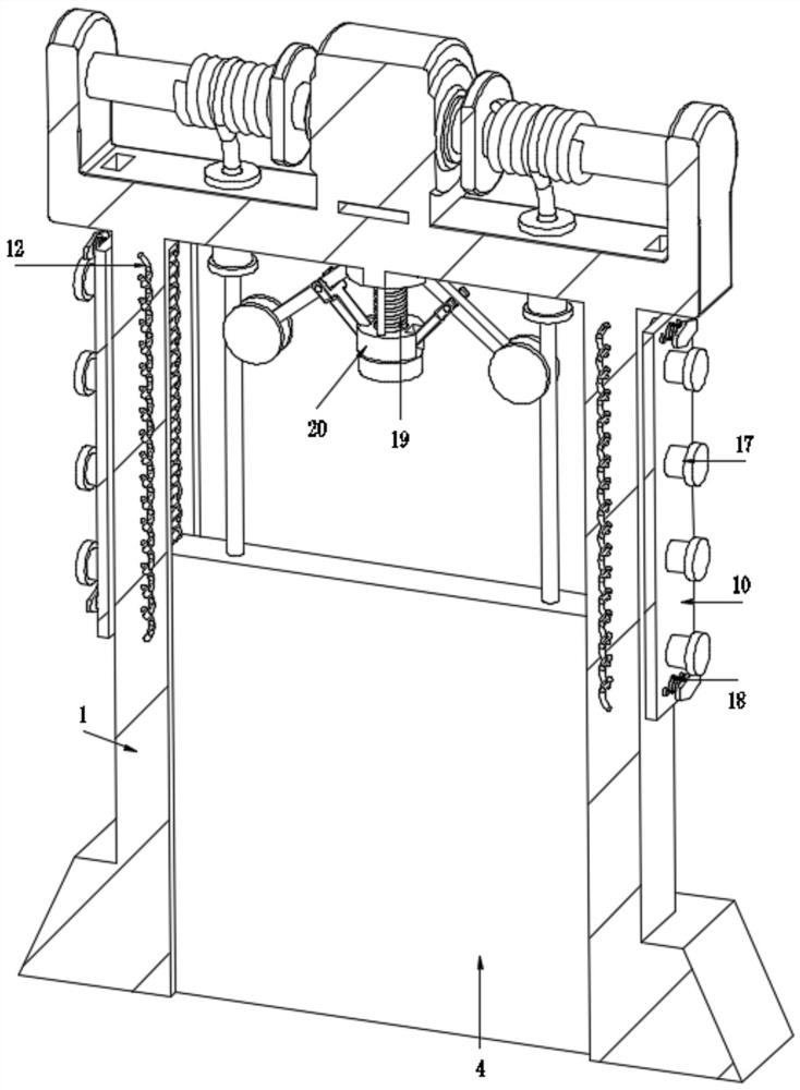
[0031] see Figure 1-7 , the present invention provides a technical solution:

[0032] A self-locking safety gate for water conservancy projects, comprising a beam column 1 and a top beam 2 fixedly connected to the top of the beam column 1, and a guide chute 3 is opened on the inner side of the beam column 1, and a gate 4 is slidably connected to the inside of the guide chute 3, and the top beam 2 The top is equipped with a lifting assembly for lifting the gate 4....


PUM


Abstract

The invention disscloses a hydraulic engineering safety gate capable of being self-locked, and belongs to the technical field of hydraulic gates. The hydraulic engineering safety gate comprises beam columns and a top beam fixedly connected with the tops of the beam columns, guide sliding grooves are formed in the inner sides of the beam columns, gates are slidably connected into the guide sliding grooves, bearing racks are fixedly connected to the two sides of the gates, and a plurality of swing teeth are evenly and rotatably connected into the guide sliding grooves; linkage shafts are fixedly connected to the ends of the swing teeth, the linkage shafts penetrate through the ends of the guide sliding grooves and are jointly and rotationally connected with synchronous plates, inner side clamping strips are fixedly connected to the side walls of the synchronous plates, limiting insertion frames are slidably connected to the side walls of the beam columns, limiting insertion teeth are fixedly connected to the side walls of the limiting insertion frames, and the limiting insertion teeth and the inner side clamping strips are matched to be used for bearing the synchronous plates. According to the hydraulic engineering safety gate capable of being self-locked, through cooperation of the teeth of a plurality of bearing clamping teeth and the swing teeth, the weight of the gate is dispersed to each stress tooth, so that the gate is stably borne and self-locked at any time, the opening and closing response speed of the gate is high, a lifting assembly is prevented from being stressed, and the opening safety of the gate is guaranteed.

Description

technical field [0001] The invention relates to the technical field of water conservancy gates, in particular to a self-locking safety gate for water conservancy projects. Background technique [0002] The gate is used to close and open the control facility of the discharge channel, an important part of the hydraulic structure, which can be used to intercept the water flow, control the water level, adjust the flow, discharge sediment and floating objects, etc. With the continuous development of science and technology, water conservancy Gate equipment is widely used because of its unique advantages. Closing the gate can block floods, keep tides or raise the upstream water level to meet social water needs such as irrigation, power generation, shipping, aquatic products, and environmental protection; opening the gate can discharge floods, drain waterlogged, Sand flushing or regulating downstream water flow is extremely important for water conservancy projects, so it is also ext...

Claims


Application Information

Patent Timeline
IPC IPC(8): E02B7/26E02B7/36
CPCE02B7/26E02B7/36
Inventor 战祥刚
Owner 战祥刚
Why Eureka
Try Eureka