
Motor iron core progressive stamping die

A stamping die and iron core technology, which is applied in the field of motor iron core processing equipment, can solve the problems of low processing efficiency, unfavorable batch processing and production, high cost, etc., and achieve the effect of improving processing efficiency

Pending Publication Date: 2021-11-23
宁波建欣精密模具有限公司
View PDF0 Cites 0 Cited by
  • Summary
  • Abstract
  • Description
  • Claims
  • Application Information

AI Technical Summary

Problems solved by technology

[0003] In the prior art, the stamping process of this type of iron core 1 is usually completed in one stamping process, that is, the stamping of the intermediate tooth portion 1.1 and the blanking of the finished product are completed in one stamping process. In this way, there are different intermediate The iron cores 1 of the tooth part 1.1 all need to make corresponding stamping dies according to their respective sizes. After the iron cores 1 of various sizes are stamped separately, they are manually stacked. This method has low processing efficiency and high cost. , not conducive to mass production

Method used


Image

  • Motor iron core progressive stamping die
  • Motor iron core progressive stamping die
  • Motor iron core progressive stamping die

Examples


Embodiment Construction

[0023] In order to make the above objects, features and advantages of the present invention more comprehensible, specific embodiments of the present invention will be described in detail below in conjunction with the accompanying drawings.

[0024] In the description of the present invention, it should be noted that the orientation or positional relationship indicated by the terms "upper end", "lower end", "inner wall" and "outer wall" are based on the orientation or positional relationship shown in the accompanying drawings, and are only In order to facilitate the description of the present invention and simplify the description, it does not indicate or imply that the device or element referred to must have a specific orientation, be constructed and operated in a specific orientation, and thus should not be construed as limiting the present invention. In addition, in the description of the present invention, the terms "first" and "second" are only for convenience of descriptio...


PUM

PropertyMeasurementUnit
thicknessaaaaaaaaaa

Abstract

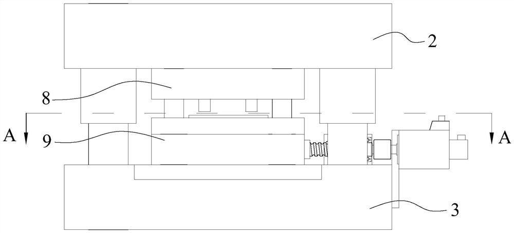
The invention provides a motor iron core progressive stamping die. The motor iron core progressive stamping die comprises an upper die base and a lower die base, wherein a blanking stamping die is arranged between the upper die base and the lower die base, the blanking stamping die comprises a blanking male die arranged on the upper die base and a blanking female die arranged on the lower die base, a stamping sub-die used for stamping a middle tooth part on an iron core is arranged between the upper die base and the lower die base in a sliding mode in the Y-axis direction, and the stamping sub-die and the blanking stamping die are sequentially arranged in the X-axis direction; and a driving mechanism used for driving the stamping sub-die to slide is arranged on the lower die base. According to the motor iron core progressive stamping die, iron cores with various sizes can be stamped only by adopting one set of die, the production efficiency is high, and large-batch production can be met.

Description

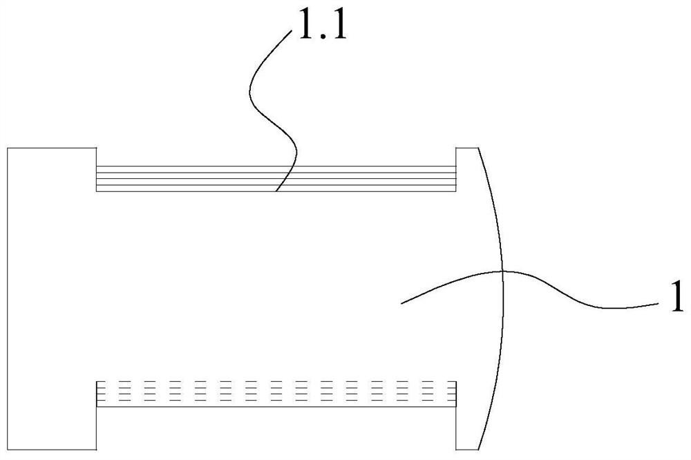
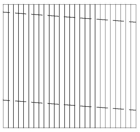
technical field [0001] The invention relates to the technical field of motor core processing equipment, in particular to a progressive stamping die for a motor core. Background technique [0002] The stator core block of the servo motor is assembled and welded by several iron core blocks punched out by a stamping die. like figure 1 , 2 As shown, each iron core block is formed by stacking several silicon steel sheets with a thickness of 0.5mm, and the two sides of the middle position of each iron 1 have corresponding middle teeth 1.1, and multiple iron cores 1 The intermediate teeth 1.1 in the middle of the stacked iron core blocks are inclined, that is, the sizes of the intermediate teeth 1.1 of each iron core 1 are different. [0003] In the prior art, the stamping process of this type of iron core 1 is usually completed in one stamping process, that is, the stamping of the intermediate tooth portion 1.1 and the blanking of the finished product are completed in one stamp...

Claims


Application Information

Patent Timeline
Patent Type & Authority Applications(China)
IPC IPC(8): B21D37/08B21D37/12B21D28/00B21D35/00H02K15/02
CPCB21D37/08B21D37/12B21D28/00B21D35/002H02K15/02
Inventor 谢梅
Owner 宁波建欣精密模具有限公司
Learn More