Monostable magnetic suspension type damping device and calculation method of magnetic suspension force of monostable magnetic suspension type damping device

A vibration reduction device and magnetic levitation technology, which is applied in the direction of shock absorbers, magnetic springs, inertial effect shock absorbers, etc., can solve the problems of excessive modification of the main structure, limited application environment, unfavorable universalization, etc., and achieve the effect of vibration reduction Improve and reduce the volume of the space, which is beneficial to the effect of miniaturization design

Active Publication Date: 2021-11-23
TIANJIN UNIV
View PDF8 Cites 0 Cited by
  • Summary
  • Abstract
  • Description
  • Claims
  • Application Information

AI Technical Summary

Problems solved by technology

NES researchers realized the design of bistable NES through the arrangement of rectangular magnets. However, this structure is often too large, and the main structure is modified too much, which has great restrictions on the application environment and is not conducive to universalization. Therefore, its There is still a lot of room for improvement in the vibration reduction effect

Method used


Image

  • Monostable magnetic suspension type damping device and calculation method of magnetic suspension force of monostable magnetic suspension type damping device
  • Monostable magnetic suspension type damping device and calculation method of magnetic suspension force of monostable magnetic suspension type damping device
  • Monostable magnetic suspension type damping device and calculation method of magnetic suspension force of monostable magnetic suspension type damping device

Examples


Embodiment Construction

[0037]The technical solutions of the present invention will be further described below in conjunction with the accompanying drawings and examples. It should be noted that although the accompanying drawings in the description describe the embodiment, the implementation is only illustrative rather than restrictive. Without departing from the gist of the present invention and the protection scope of the claims, the materials and dimensional parameters of each component can also be changed, and these all belong to the protection scope of the present invention.

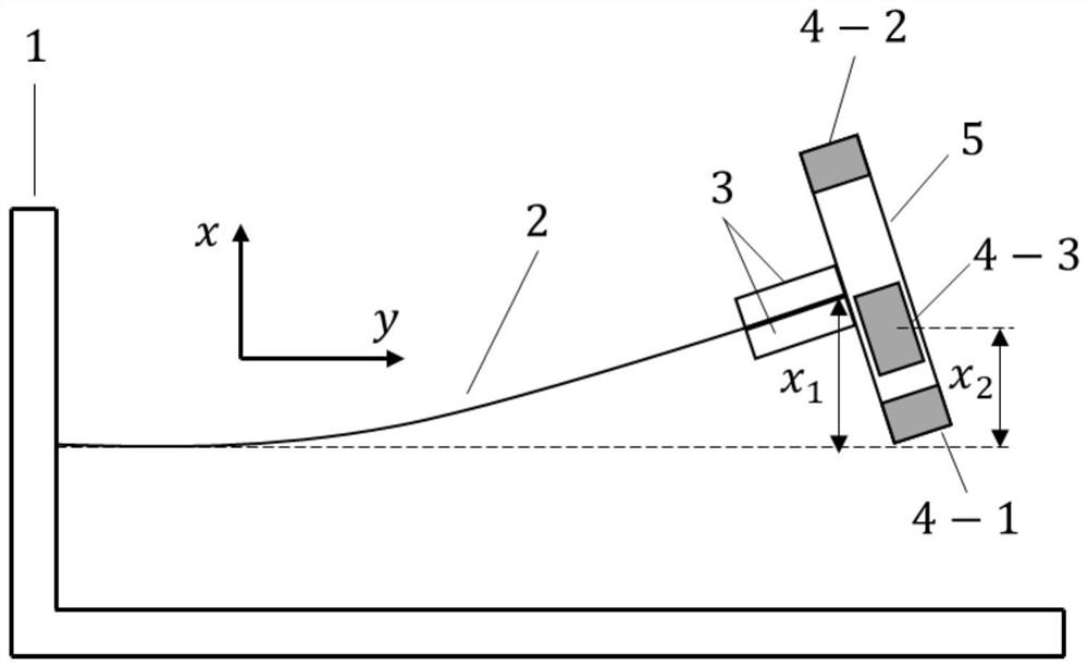
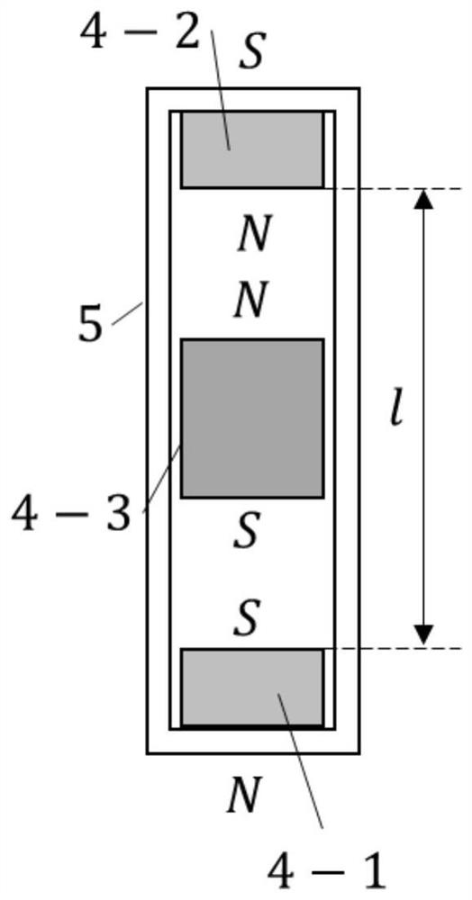
[0038] The technical solution includes the structure of the monostable magnetic levitation damping system, the connection mode and connection position of the shock absorber and the cantilever beam, the calculation steps of the monostable magnetic levitation force in the shock absorber, and the calculation method of the optimal magnet spacing in the shock absorber.

[0039] combined with figure 1 And attached figure 2 , ...


PUM

PropertyMeasurementUnit
Lengthaaaaaaaaaa
Diameteraaaaaaaaaa
Outer diameteraaaaaaaaaa

Abstract

The invention discloses a monostable magnetic suspension type vibration reduction device for cantilever beam vibration and a calculation method of magnetic suspension force of the monostable magnetic suspension type vibration reduction device. The monostable magnetic suspension type vibration reduction device comprises a monostable magnetic suspension type vibration reduction device calculation step and a magnetic suspension force calculation step. According to the structure of the device, a cantilever beam is fixed to a base stand column, a mass block and a fastener are fixed to the free end of the cantilever beam, and a magnetic suspension type dynamic vibration absorber is composed of a magnetic suspension tube and three magnets. Two fixed magnets are arranged at the upper end and the lower end of the magnetic suspension tube, a third magnet is arranged between the fixed magnets, and the third magnet is suspended in the magnetic suspension tube by setting the polarity of the magnets. Meanwhile, a calculation method for the magnetic induction intensity, the magnetic force between the two magnets and the magnetic suspension resultant force is given. The cantilever beam can be damped only by setting the sizes of the three magnets and fixing the distance between the two magnets. And a new technical method is provided for application of the nonlinear dynamic vibration absorber, the occupied volume of the vibration absorber is reduced, and the improvement of the vibration reduction effect is facilitated.

Description

technical field [0001] The invention belongs to the field of electromechanical technology, and in particular relates to a vibration damping device capable of absorbing and dissipating vibration energy and providing reaction force to a main structure cantilever beam. Background technique [0002] Vibration is a common phenomenon in mechanical engineering. Vibration will not only affect the normal operation of the structure, but also cause damage to the structure itself. Among many vibrating structures, cantilever beams are widely used due to their simple structure, convenient operation, and strong flexibility. However, the general cantilever beam structure has poor mechanical performance because it is easily affected by vibration. How to weaken the vibration of the cantilever beam has always attracted the attention of researchers. The vibration reduction methods of cantilever beam structures are mainly divided into active vibration reduction, semi-active vibration reduction ...

Claims


Application Information

Patent Timeline
IPC IPC(8): F16F7/10F16F6/00G06F30/17
CPCF16F7/1011F16F6/005G06F30/17F16F2222/06F16F2222/08
Inventor 冷永刚陈潇雨苏徐昆孙帅令张雨阳许俊杰
Owner TIANJIN UNIV
Why Eureka
Try Eureka