Supercharge Your Innovation With Domain-Expert AI Agents!

Hydraulic high-precision automatic leveling device with self-locking function

An automatic leveling, hydraulic technology, applied in the direction of mechanical equipment, engine frame, non-rotational vibration suppression, etc., can solve the problems of leveling failure, mechanical equipment rollover, low precision, etc., to save manual adjustment, prevent Damage, the effect of high adjustment accuracy

Active Publication Date: 2021-11-23
WU NA
View PDF19 Cites 0 Cited by
  • Summary
  • Abstract
  • Description
  • Claims
  • Application Information

AI Technical Summary

Problems solved by technology

[0003]The traditional method of leveling mechanical equipment is to place shims at one end of the machine base at the required height, and also place them on both sides of the anchor bolts at the other end. Use a spirit level to find the level on the processing surface of the machine base, and then screw on the anchor bolts after leveling, and finally add a shim to the anchor bolts, find the level, and screw on the anchor bolts after leveling. Or use other hand-twist-type foundation leveling devices to replace the foundation bolts for leveling, such as a kind of mechanical equipment leveling device disclosed in the prior art (CN 210771049 U), comprising a load-bearing plate, the rear side of the upper surface of the load-bearing plate The middle position is fixed with a threaded column, the outer surface of the threaded column is sleeved with a screw barrel, the upper end surface of the threaded column is against the lower surface of the receiving body, the upper part of the receiving body is fixedly provided with a connecting hole, and the receiving body is rotatably connected to the lower part of the connecting block. The block is fixedly connected to the lower surface of the bearing plate, and the size of the bearing plate is the same as that of the load-bearing plate. The two sides between the receiving plate and the load-bearing plate are fixedly connected with brackets, and the middle of the bracket is connected with a turntable. , the rear part is provided with a support structure, although the multi-directional tilt adjustment of the leveling plate can be realized, but because the angle of tilt adjustment is too large in the actual use process, the mechanical equipment will roll over, and this kind of hand-tightening bolt is used The way of leveling is that the damage to the bolts is great. Once the weight of the mechanical equipment exceeds the bearing capacity of the bolts, the leveling will fail; the second is that the leveling accuracy is low, which cannot meet the current increasingly sophisticated mechanical equipment. Supporting leveling requirements

Method used


Image

  • Hydraulic high-precision automatic leveling device with self-locking function
  • Hydraulic high-precision automatic leveling device with self-locking function
  • Hydraulic high-precision automatic leveling device with self-locking function

Examples


Embodiment 1

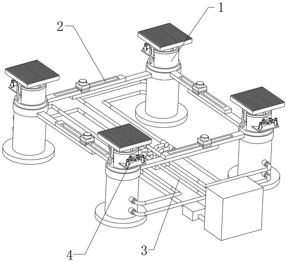
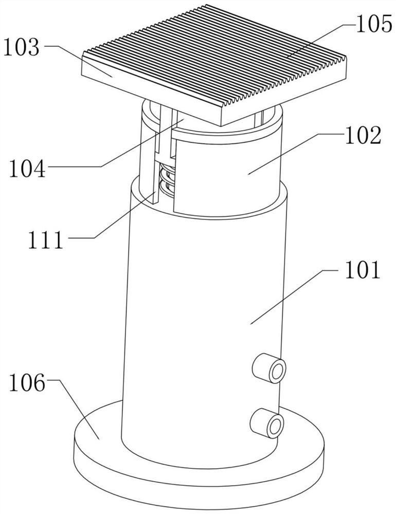
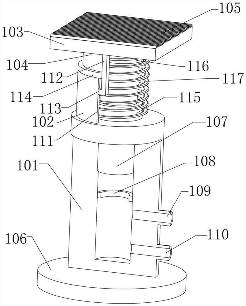
[0038] Examples of automatic leveling of mechanical equipment carried by the present invention are as follows: figure 1 , image 3 , Figure 5 , Image 6 , Figure 7 , Figure 8 As shown, the four sets of leveling assemblies 1 are respectively arranged at the corners of the automatic leveling device, and the whole is fixed on the operation plane by the fixed base 106, and the lifting limit base 102 of a cylindrical structure is fixed on the outer side of the top of the oil cylinder main body 101, Both ends of the lifting limit base 102 are symmetrically provided with lifting grooves 111, and a lifting shaft 104 is fixed on the outside of the bottom of the leveling top plate 103. Seat 112, the card platform 113 is fixed on the bottom of the lifting seat 112, and the card platform 113 can slide up and down in the lifting groove 111. The top limit position 114 is fixed on the top of the lifting limit base 102, and the top limit position 114 presses the card platform 113 on th...

Embodiment 2

[0046] The present invention realizes the mechanical locking of the leveling top plate 103 in each group of leveling assemblies 1 after the leveling is completed. figure 1 , figure 2 , Figure 4 , Figure 10 , Figure 11 with Figure 12 As shown, the outer side of the lifting limit base 102 in each group of leveling assemblies 1 is provided with a locking assembly 4 for locking the leveling top plate 103, the locking groove 401 is opened on the outer wall of the lifting shaft 104, and the lifting limit base 102 On the position corresponding to the outer wall and the locking groove 401, a locking position 402 is provided, and a locking cylinder 403 is inserted into the locking position 402. The front end of the locking cylinder 403 can be pressed against any position in the locking groove 401. Symmetrically fixed fixed rotation 404, the left and right sides of the rear end of the lock cylinder 403 are symmetrically fixed with linkage rotation 405, each set of fixed rotatio...


PUM


Abstract

The invention provides a hydraulic high-precision automatic leveling device with a self-locking function and belongs to the technical field of leveling of mechanical equipment. The hydraulic high-precision automatic leveling device comprises leveling assemblies, auxiliary rod assemblies, hydraulic power assemblies and locking assemblies, wherein four groups of leveling assemblies are connected with each other through the auxiliary rod assemblies to form a quadrangle as same as a mechanical equipment base; main power for lifting of each group of leveling assemblies is provided by the same hydraulic power assembly; the hydraulic power assembly is communicated with oil cylinder main bodies in the leveling assemblies through an oil inlet valve and an oil returning valve which are integrated, so that any group of oil cylinder rods can be independently driven to lift; a flat spring is further arranged each leveling assembly; the flat springs can buffer return oil of the oil cylinder main bodies and protect the mechanical equipment needed to be leveled and the leveling assemblies; through the locking assemblies arranged on lifting limiting bases, the hydraulic power can be eliminated and converted into mechanical locking after locking lifting shafts at any height positions; and the hydraulic high-precision automatic leveling device is energy-saving, safe and reliable.

Description

technical field [0001] The invention relates to the technical field of mechanical equipment leveling, in particular to a hydraulic high-precision automatic leveling device with a self-locking function. Background technique [0002] The leveling and alignment work of equipment installation is carried out after the equipment is hoisted in place and before the equipment is operated. The task is to install the equipment to meet the quality standards required by the technology through adjustment. The precise leveling of equipment has an important impact on the work quality and efficiency of subsequent equipment. [0003] The traditional method of leveling mechanical equipment is to place shim iron at the required height on one end of the machine base, and also place shim iron at the required height on both sides of the anchor bolts at the other end, and then use a level to adjust the level on the processing surface of the machine base. Look up the level, screw on the anchor bolt...

Claims


Application Information

Patent Timeline
IPC IPC(8): F16M7/00F16F15/06
CPCF16M7/00F16F15/06F16M2200/028
Inventor 吴娜
Owner WU NA
Features
  • R&D
  • Intellectual Property
  • Life Sciences
  • Materials
  • Tech Scout
  • Unparalleled Data Quality
  • Higher Quality Content
  • 60% Fewer Hallucinations
Learn More