PCB (Printed Circuit Board) visual inspection equipment

A PCB board and visual inspection technology, applied in the field of SMT processing and inspection equipment, can solve problems such as affecting the detection accuracy of PCB boards, and achieve the effects of improving detection accuracy, improving cleaning effect, and reducing cleaning dead ends.

Pending Publication Date: 2021-11-23
深圳市中纬智能有限公司
View PDF0 Cites 2 Cited by
  • Summary
  • Abstract
  • Description
  • Claims
  • Application Information

AI Technical Summary

Problems solved by technology

[0005] In order to improve the problem that impurities affect the detection accuracy of PCB boards, this application provides a visual detection equipment for PCB boards

Method used


Image

  • PCB (Printed Circuit Board) visual inspection equipment
  • PCB (Printed Circuit Board) visual inspection equipment
  • PCB (Printed Circuit Board) visual inspection equipment

Examples


Embodiment Construction

[0039] The following is attached Figure 1-7 The application is described in further detail.

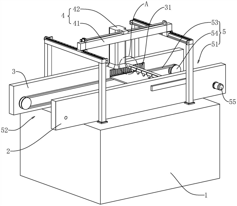
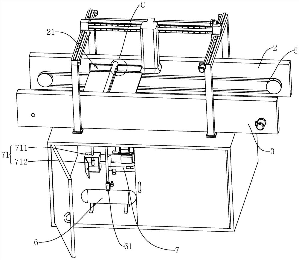
[0040] The embodiment of the present application discloses a visual inspection device for a PCB board. refer to figure 1 , a kind of PCB board visual detection equipment comprises frame body 1, first track plate 2, second track plate 3, visual detection device 4 and cleaning device, and first track plate 2 and second track plate 3 are all bolted to frame body 1. The first track plate 2 and the second track plate 3 are arranged opposite to each other, and there is a passage for the PCB board to pass between the first track plate 2 and the second track plate 3 . The opposite board surfaces of the first track plate 2 and the second track plate 3 are all provided with a transfer rail 5, the transfer rail 5 has a feed port 51 and a discharge port 52, and the transfer rail 5 is used to transfer the PCB board to the visual inspection device 4. detection position. Before the conveying ra...


PUM


Abstract

The invention relates to the field of SMT (Surface Mount Technology) processing inspection equipment, in particular to PCB (Printed Circuit Board) visual inspection equipment, which comprises a frame body, a first track plate, a second track plate and a visual inspection device. A channel for a PCB to pass through is reserved between the first track plate and the second track plate. Conveying rails are arranged on opposite plate surfaces of the first track plate and the second track plate, and are used for conveying a PCB to a detection position of the visual detection device. The opposite surfaces of the first track plate and the second track plate are respectively provided with an impurity inlet and a gas outlet which are oppositely arranged. The frame body is provided with a gas bag. The gas bag is provided with an electromagnetic pulse valve for gas to flow out. An outlet pipeline of the electromagnetic pulse valve is connected to the gas outlet. The gas in the gas bag flows into the gas outlet through the electromagnetic pulse valve, and the gas is guided by the gas outlet to blow impurities attached to the surface of the PCB into the impurity inlet. By adoption of the PCB visual inspection equipment, the problem that the detection precision of a PCB is affected by impurities is solved.

Description

technical field [0001] The present application relates to the field of SMT processing inspection equipment, in particular to a visual inspection equipment for PCB boards. Background technique [0002] SMT patch refers to the abbreviation of a series of process processes processed on the basis of PCB. SMT is Surface Mount Technology (Surface Mount Technology), which is the most popular technology and process in the electronics assembly industry. Among them, after the end of each process of SMT placement, the PCB board will be inspected to detect errors in the pre-process early and reduce losses. [0003] Automated optical inspection (AOI for short) is widely used in SMT placement technology. Automatic optical inspection During automatic inspection, the machine automatically scans the PCB through a horizontally moving camera, collects images, compares the tested solder joints with the qualified parameters in the database, and checks out the defects on the PCB through image p...

Claims


Application Information

Patent Timeline
Patent Type & Authority Applications(China)
IPC IPC(8): G01N21/956G01N1/34B08B5/02B08B1/00B08B13/00
CPCG01N21/956G01N21/95607G01N1/34B08B5/02B08B1/005B08B13/00G01N2021/95638G01N2021/95646G01N2021/95615
Inventor 周益和杨达利
Owner 深圳市中纬智能有限公司
Why Eureka
Try Eureka