
Dual-frequency dielectric patch antenna with frequency tunable function

A patch antenna, medium technology, applied in the direction of antenna, antenna grounding device, radiating element structure, etc.

Active Publication Date: 2021-11-23
NANTONG UNIVERSITY
View PDF7 Cites 1 Cited by
  • Summary
  • Abstract
  • Description
  • Claims
  • Application Information

AI Technical Summary

Problems solved by technology

However, so far, no researchers have proposed frequency reconfigurable dual-band antennas based on dielectric patch antennas.

Method used


Image

  • Dual-frequency dielectric patch antenna with frequency tunable function
  • Dual-frequency dielectric patch antenna with frequency tunable function
  • Dual-frequency dielectric patch antenna with frequency tunable function

Examples


Embodiment Construction

[0023] The present invention will be further described below in conjunction with the accompanying drawings and specific embodiments.

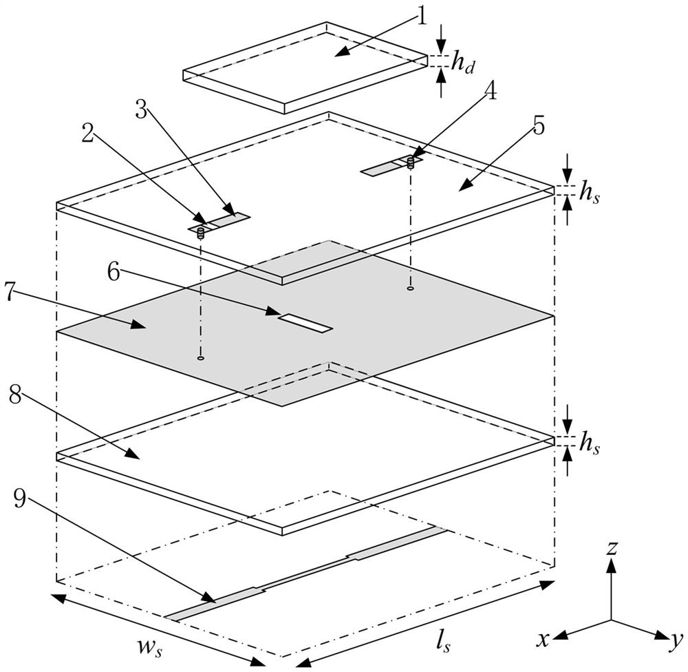
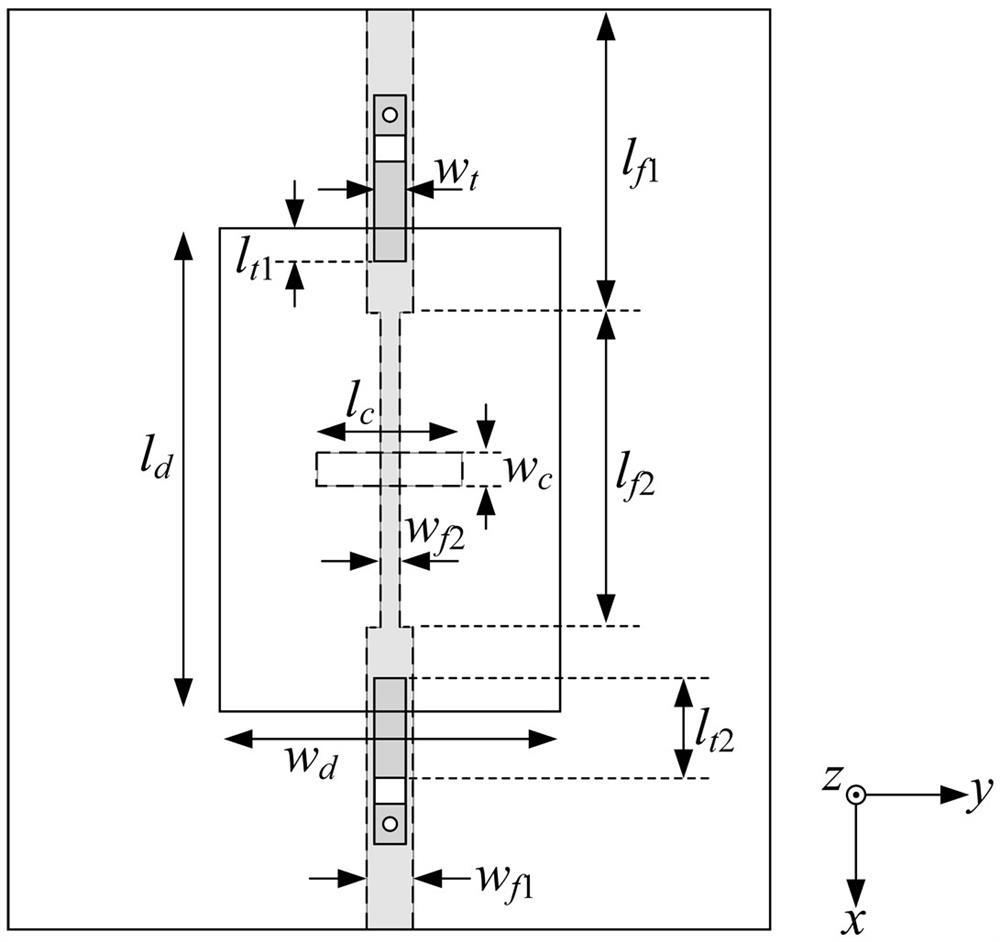
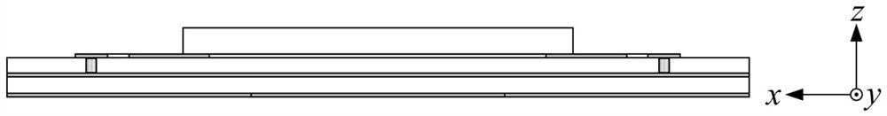
[0024] Such as Figure 1 to Figure 3 As shown, this embodiment has a dual-frequency dielectric patch antenna with frequency tunable function, which is along the xoz Axi-plane symmetry. The antenna is mainly composed of three parts, namely a rectangular dielectric patch 1, an upper dielectric substrate 5 with a tuning circuit, and a lower dielectric substrate 8 with a slot coupling feeding structure. The metal reflective floor 7 , the upper dielectric substrate 5 and the dielectric patch 1 stacked sequentially from bottom to top constitute a dielectric patch resonator. The dielectric patch 1 is located at the center of the upper dielectric substrate 5 , and the distance from the side of the upper dielectric substrate 5 to the nearest side of the dielectric patch 1 is approximately equal. A microstrip feeder 9 for coupling and feeding is prov...


PUM


Abstract

The invention relates to a dual-frequency dielectric patch antenna with a frequency tunable function, which comprises a lower dielectric substrate, a metal reflection floor, an upper dielectric substrate and a rectangular dielectric patch which are sequentially stacked from bottom to top. A frequency tuning structure is arranged between the rectangular dielectric patch and the upper dielectric substrate, the lower surface of the lower dielectric substrate is provided with a microstrip feed line for coupling differential feed, and the metal reflection floor is provided with a coupling gap corresponding to the microstrip feed line. The invention provides a frequency-reconfigurable dual-frequency dielectric patch antenna working in a dominant mode TM10 and a high-order mode anti-phase TM20 for the first time. Because the sensitivities of the two modes to the length change of the dielectric patch are different, the electrical length of the dielectric patch is changed by embedding a pair of microstrip line parts loaded with variable capacitance diodes into the two sides of the rectangular dielectric patch resonator in a targeted manner, so that under the condition that the frequency and radiation performance of a main mode TM10 are not influenced, the frequency of the high-order mode inverted TM20 is independently tuned.

Description

technical field [0001] The invention relates to the technical field of wireless communication, in particular to a dual-frequency dielectric patch antenna with a frequency tunable function. Background technique [0002] With the rapid development of wireless communication technology, scarce spectrum resources and complex electromagnetic environment make the design of high-performance antennas more challenging. In order to meet the requirements of multi-function, easy integration, large capacity and low cost of modern wireless communication, dual-band wireless communication system has received extensive attention. At the same time, the contradiction between increasing wireless applications and limited antenna installation space is becoming more and more obvious, and frequency reconfigurable antennas have also received more and more attention. It can dynamically adjust the operating frequency and provide noise suppression in unused frequency bands, reducing the system's filter...

Claims


Application Information

Patent Timeline
IPC IPC(8): H01Q1/38H01Q1/48H01Q13/08H01Q15/00
CPCH01Q1/38H01Q1/48H01Q13/08H01Q15/002Y02D30/70
Inventor 陈建新唐世昌王雪颖张扬
Owner NANTONG UNIVERSITY
Learn More