
Outer rotor permanent magnet induction motor and working method

A technology of induction motor and external rotor, which is applied in the direction of electric components, magnetic circuit rotating parts, magnetic circuit, etc., can solve the problem that the speed regulation performance is not as good as that of the three-phase induction motor, the operating efficiency and power factor are low, and the system complexity and cost are increased. and other issues, to achieve the effect of saving energy and reducing consumption, optimizing the waveform, and benefiting the power factor and efficiency

Active Publication Date: 2021-11-23
QILU UNIV OF TECH
View PDF14 Cites 0 Cited by
  • Summary
  • Abstract
  • Description
  • Claims
  • Application Information

AI Technical Summary

Problems solved by technology

However, there are still some deficiencies in the application of three-phase wound induction motors, which are mainly manifested in two aspects. One is that the starting current is too large. In order to reduce the starting current, a large starting resistance must be connected in series. low, both of these aspects will result in a large power loss
[0003] Permanent magnet motors do not require excitation windings for excitation, and have the advantages of high efficiency, high power density, high torque density, and simple rotor structure. However, permanent magnet motors cannot adjust the magnetic field because the polarity of the permanent magnets is fixed. It is not as good as a three-phase induction motor, and the permanent magnet motor usually needs to be powered by a frequency converter to start, which increases the complexity and cost of the system

Method used


Image

  • Outer rotor permanent magnet induction motor and working method
  • Outer rotor permanent magnet induction motor and working method
  • Outer rotor permanent magnet induction motor and working method

Examples


Embodiment Construction

[0029] In order to make the purpose, features and advantages of the present invention more obvious and understandable, the technical solutions protected by the present invention will be clearly and completely described below using specific embodiments and accompanying drawings. Obviously, the implementation described below Examples are only some embodiments of the present invention, but not all embodiments. Based on the embodiments in this patent, all other embodiments obtained by persons of ordinary skill in the art without creative efforts fall within the protection scope of this patent.

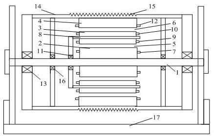
[0030] As shown in the figure, an external rotor motor includes a main shaft 1, a stator 2, a first rotor 3 and a second rotor 4 are arranged on the outside of the main shaft 1 in turn; the main shaft 1 is fixedly mounted on a main shaft fixing bracket 17; A first air gap 5 is provided between the stator 2 and the first rotor 3, and a second air gap 6 is provided between the first rotor 1 ...


PUM


Abstract

The invention discloses an outer rotor permanent magnet induction motor and a working method. The outer rotor permanent magnet induction motor comprises a main shaft, and the outer side of the main shaft is sequentially provided with a stator, a first rotor and a second rotor; a first air gap is arranged between the stator and the first rotor, and a second air gap is arranged between the first rotor and the second rotor; the stator comprises a stator iron core, a stator winding is arranged on the stator iron core, and the stator winding is a three-phase symmetrical alternating current winding; the first rotor comprises a first rotor support, the first rotor support is provided with a first rotor iron core, and the first rotor iron core is provided with a first rotor starting winding and a permanent magnet. The second rotor comprises a second rotor iron core, and a second rotor winding is arranged on the second rotor iron core; the starting current of the motor is effectively reduced, and the power density, electromagnetic torque and efficiency of the motor are improved.

Description

technical field [0001] The invention relates to the technical field of motors, in particular to an outer rotor permanent magnet induction motor and a working method. Background technique [0002] Three-phase wound induction motors are widely used in places that require high starting performance and speed regulation performance because the rotor can be connected with an external resistor. However, there are still some deficiencies in the application of three-phase wound induction motors, which are mainly manifested in two aspects. One is that the starting current is too large. In order to reduce the starting current, a large starting resistance must be connected in series. Low, both of these aspects will cause a lot of power loss. [0003] Permanent magnet motors do not require excitation windings for excitation, and have the advantages of high efficiency, high power density, high torque density, and simple rotor structure. However, permanent magnet motors cannot adjust the ...

Claims


Application Information

Patent Timeline
Patent Type & Authority Applications(China)
IPC IPC(8): H02K16/02H02K1/30H02K1/27H02K21/46H02P23/26
CPCH02K16/02H02K1/30H02K1/2786H02K21/46H02P23/26
Inventor 刁统山张绍杰张金烽
Owner QILU UNIV OF TECH
Learn More