Supercharge Your Innovation With Domain-Expert AI Agents!

Motor rotor position detection method and device and motor controller

A technology of motor rotor and current, applied in the field of motor controller and motor rotor position detection, can solve the problems of low detection accuracy, deviation between rotor position and actual value, etc., and achieve the effect of improving accuracy

Pending Publication Date: 2021-11-23
GUANGDONG WELLING ELECTRIC MACHINE MFG +1
View PDF0 Cites 0 Cited by
  • Summary
  • Abstract
  • Description
  • Claims
  • Application Information

AI Technical Summary

Problems solved by technology

At present, when detecting the rotor position, usually due to the interactive coupling effect of the direct axis and the quadrature axis in the motor, the detected rotor position will deviate from the actual value, and the detection accuracy is low.

Method used


Image

  • Motor rotor position detection method and device and motor controller
  • Motor rotor position detection method and device and motor controller
  • Motor rotor position detection method and device and motor controller

Examples


Embodiment Construction

[0045] Embodiments of the present invention are described in detail below, examples of which are shown in the drawings, wherein the same or similar reference numerals designate the same or similar elements or elements having the same or similar functions throughout. The embodiments described below by referring to the figures are exemplary and are intended to explain the present invention and should not be construed as limiting the present invention.

[0046] The motor inductance detection method, device and motor controller according to the embodiments of the present invention will be described below with reference to the accompanying drawings.

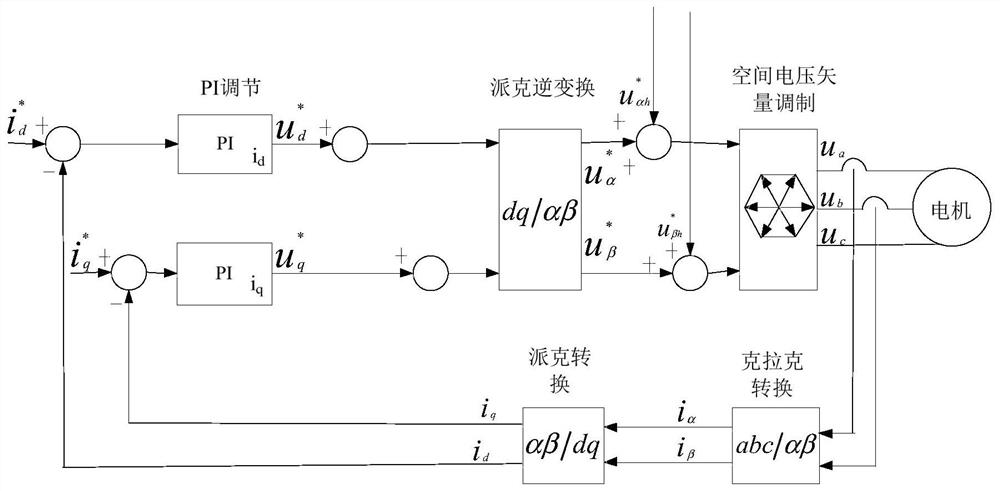
[0047] It should be noted that, in this embodiment, a two-phase stationary coordinate system α-β can be defined, and a two-phase rotating coordinate system d-q is established on the motor rotor, and then the coordinate system d-q rotates synchronously with the rotor, and the d-axis (direct axis ) is the direction of the rotor magnetic...


PUM


Abstract

The invention provides a motor rotor position detection method and device and a motor controller. The method comprises the steps of obtaining a current positive-sequence component with the frequency of f and a current negative-sequence component with the frequency of f1 in a driving current after a first interference signal with the frequency of f is injected into a motor driving loop, wherein f1 is less than f; acquiring a current driving current feedback value; determining a current reference coefficient value according to the current driving current feedback value; determining a current deviation angle according to the current reference coefficient value, the amplitude of the the current positive-sequence component with the frequency of f and the amplitude of the current negative-sequence component with the frequency of f1; and determining the current position of the motor rotor according to the current deviation angle. According to the method, the deviation angle of the motor rotor is determined according to the injected interference signal and the driving current feedback value of the motor, the position of the motor rotor is determined through the deviation angle, and the accuracy of rotor position detection can be improved.

Description

technical field [0001] The invention relates to the technical field of motors, in particular to a motor rotor position detection method, device and motor controller. Background technique [0002] Permanent magnet synchronous motors or synchronous reluctance motors have the advantages of high power density and high efficiency, and are widely used in household appliances and electric vehicles. In order to realize the stable operation of the motor without a position sensor, the rotor position detection method based on the saliency of the motor has been widely used. At present, when detecting the rotor position, usually due to the interactive coupling effect of the direct axis and the quadrature axis in the motor, the detected rotor position will deviate from the actual value, and the detection accuracy is low. Contents of the invention [0003] The present invention aims to solve one of the technical problems in the related art at least to a certain extent. [0004] For thi...

Claims


Application Information

Patent Timeline
IPC IPC(8): H02P6/18H02P21/18G01B7/00
CPCH02P6/183H02P21/18G01B7/003G01B7/00H02P6/18H02P25/026
Inventor 双波诸自强
Owner GUANGDONG WELLING ELECTRIC MACHINE MFG
Features
  • R&D
  • Intellectual Property
  • Life Sciences
  • Materials
  • Tech Scout
  • Unparalleled Data Quality
  • Higher Quality Content
  • 60% Fewer Hallucinations
Learn More