
Near-field sparse array antenna beam establishment method and device

Active Publication Date: 2021-11-23
AIR FORCE EARLY WARNING ACADEMY
View PDF6 Cites 0 Cited by
  • Summary
  • Abstract
  • Description
  • Claims
  • Application Information

AI Technical Summary

Problems solved by technology

[0004] Aiming at the defects of the prior art, the purpose of the present invention is to provide a near-field sparse array antenna beam establishment method and device, aiming to solve the problem that the existing unmanned aerial vehicle cluster array and electronic countermeasure field are not combined with each other, resulting in unmanned The problem that the antenna beam concentration cannot be judged in the process of reconnaissance target

Method used


Image

  • Near-field sparse array antenna beam establishment method and device
  • Near-field sparse array antenna beam establishment method and device
  • Near-field sparse array antenna beam establishment method and device

Examples


Embodiment 1

[0195] Simulation:

[0196] Suppose the full-directional antenna transmitted signal frequency on each drone in the drone group is 30MHz, the direction of the direction is θ = [- 180 °, 180 °], = [- 60 °, 60 °], expects the main flap beam pointing to = 0 ° direction, observation target distance is 300,000λ, the drone group is initially connected to the two-dimensional plane of the 1000λ × 1000λ, the number of total racks is 32, theoretical, the pitch distribution, the pattern distribution, the pattern distribution is more sample It is more likely to find the optimal solution, that is, the optimal effect of the synthetic beam may be better, but considering the factors such as the size, speed and position positioning error of the drone, the position between the drone is not generated. Constrain d n ≥ d min = 10λ, set to suppress the sub-flap in the synthetic beam, take Ω 1 = 0.8, = 0.2, under the distribution range of the drone group and the target distance limit, the ideal main l...

Embodiment 2

[0201] Comparative experiment verification:

[0202] The adaptive value value value change value of the ADE method and genetic method to be obtained by Monte Carlo test is run, respectively. Figure 7 As shown; wherein the number of genetic methods is 100, the hybridization rate is 0.7, the selectivity is 0.5, the variant is 0.5, and the elite reservation method is used, the remaining conditions are consistent with the simulation verification setting; the beginning of the mutant operator, ADE The method is relatively fast. As the algebra increases, the variation operator gradually decreases, so that the ADE method is gradually stable, and the final adaptation function value is 0.2624, which is less than the adaptive function value when the unit is evenly distributed. ;

[0203] After the genetic method passes through one hundred generations, the adaptation function value does not decline, indicating that the 100 generation is not sufficient to make an individual that the adaptivity...

Embodiment 3

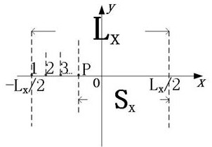
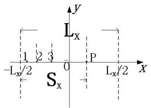
[0209] The simulation condition is set to the same, and the random error is added to the solved error when solving the adaptive function value, and the GPS navigation error is generally different from two planes perpendicular to the horizontal plane. [-0.2m, 0.2m], the error range on the vertical surface is [-0.1m, 0.1m], and the error range is added when solving the adaptive function value, because the present invention does not discuss the drone on the vertical surface The movement only focuses on the distribution formation of the drone on the horizontal plane, solving the position of the element XOY Planar formation is shown in Fig. 11 (a) and Fig. 11 (b);

[0210] Convergence in a certain ADE method iteration Figure 12 As shown, the adaptation function value is affected by the position error; the reason is that even if the cell position determination value is the same, it is affected by the position error, and its adaptation function value is different; the position error in t...


PUM


Abstract

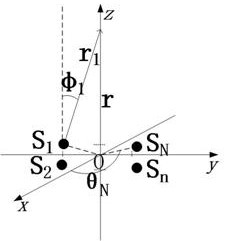
The invention provides a near-field sparse array antenna beam establishment method and device, and belongs to the field of electronic countermeasure of unmanned aerial vehicle clusters, and the method comprises the steps: taking each unmanned aerial vehicle in an unmanned aerial vehicle cluster as an array element, and taking a reconnaissance object of the unmanned aerial vehicle cluster as a target; establishing a coordinate system based on the unmanned aerial vehicle cluster by taking the center of the unmanned aerial vehicle cluster distribution area as an original point and the plane where the unmanned aerial vehicle cluster is located as an xoy plane; constructing array element distribution of the unmanned aerial vehicle cluster in combination with constraint conditions; according to an included angle between a connecting line formed by an array element and a target in the unmanned aerial vehicle cluster and a z axis and an included angle between a projection of the connecting line formed by the array element and the target in an xoy plane and an x axis, establishing a super-sparse array model corresponding to the unmanned aerial vehicle cluster; and based on the super-sparse array model, establishing a directional diagram of an antenna array synthetic beam. In the process of target reconnaissance of the unmanned aerial vehicle, whether antenna beams are concentrated or not can be judged by analyzing antenna array synthesis beams, and an optimization basis is provided for subsequent unmanned aerial vehicle array arrangement.

Description

Technical field [0001] The present invention belongs to the electronic counterming field of the drone cluster, and more particularly to an near field sparse array antenna beam establishment method and apparatus. Background technique [0002] With the popularity of drone cluster concept, through the cluster and collaboration between the drone, and equipped with a large number of all-to-the antennas, achieving low-cost distributed beamforming capacity is increasingly focusing on the public. A pseudo-phase control array with a distributed unit (ie, a distributed drone), wherein the distributed beamforming technique is one of the key technologies. This also shows that future wars are unmanned war, and the reasonable application research of drone clusters is imminent. [0003] At present, there is a literature to apply the drone cluster as a three-dimensional group array antenna, but it is set up a drone as the host, that is, the drone is not exactly the same, the second is not unmann...

Claims


Application Information

Patent Timeline
Patent Type & Authority Applications(China)
IPC IPC(8): H04B7/06G06N3/12
Inventor 冷毅张逸楠彭世蕤余国文王广学何缓杨华兵王冰切
Owner AIR FORCE EARLY WARNING ACADEMY
Learn More