
Cutting fluid recycling device for high-grade numerical control machine tool

A CNC machine tool, cutting fluid technology, applied in the direction of metal processing machinery parts, maintenance and safety accessories, solid separation, etc., can solve the problems of inconvenient movement, difficult work of removing iron filings, etc., and achieve good cleaning effect

Pending Publication Date: 2021-11-26
东莞市技师学院
View PDF0 Cites 2 Cited by
  • Summary
  • Abstract
  • Description
  • Claims
  • Application Information

AI Technical Summary

Problems solved by technology

[0004] In order to overcome the inconvenience of manual movement in the cutting fluid pool, which makes it difficult to remove iron filings, and makes it difficult to quickly make the used cutting fluid reusable, the technical problem of the present invention is to provide a A cutting fluid recovery and reuse device for high-end CNC machine tools that can quickly remove iron filings in the cutting fluid

Method used


Image

  • Cutting fluid recycling device for high-grade numerical control machine tool
  • Cutting fluid recycling device for high-grade numerical control machine tool
  • Cutting fluid recycling device for high-grade numerical control machine tool

Examples


Embodiment 1

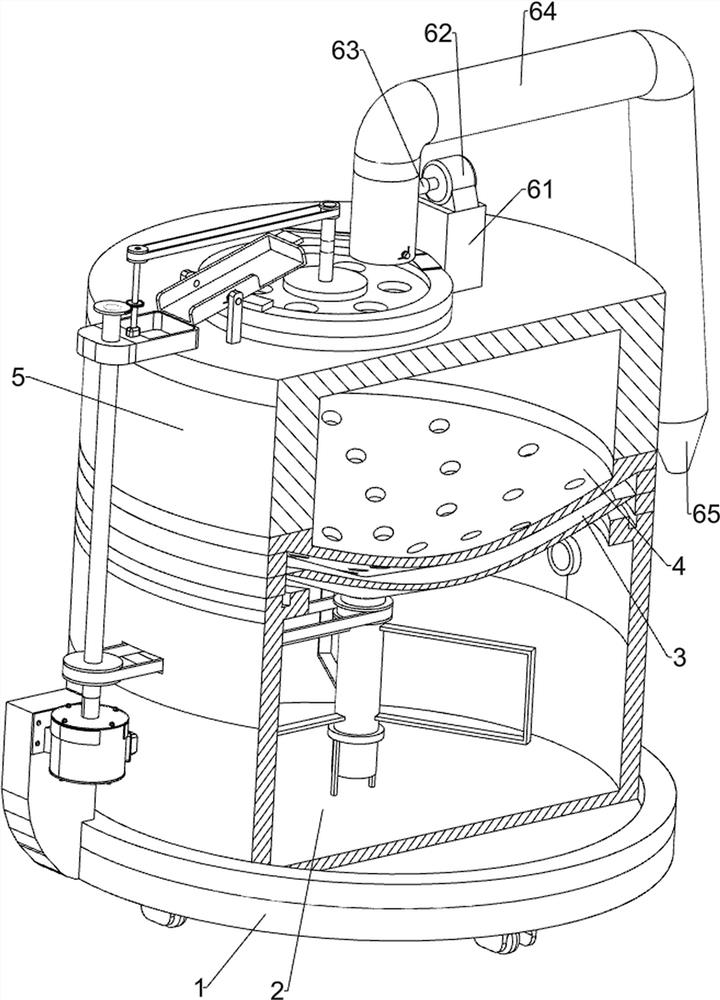
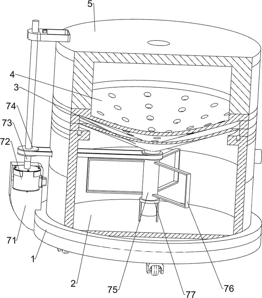
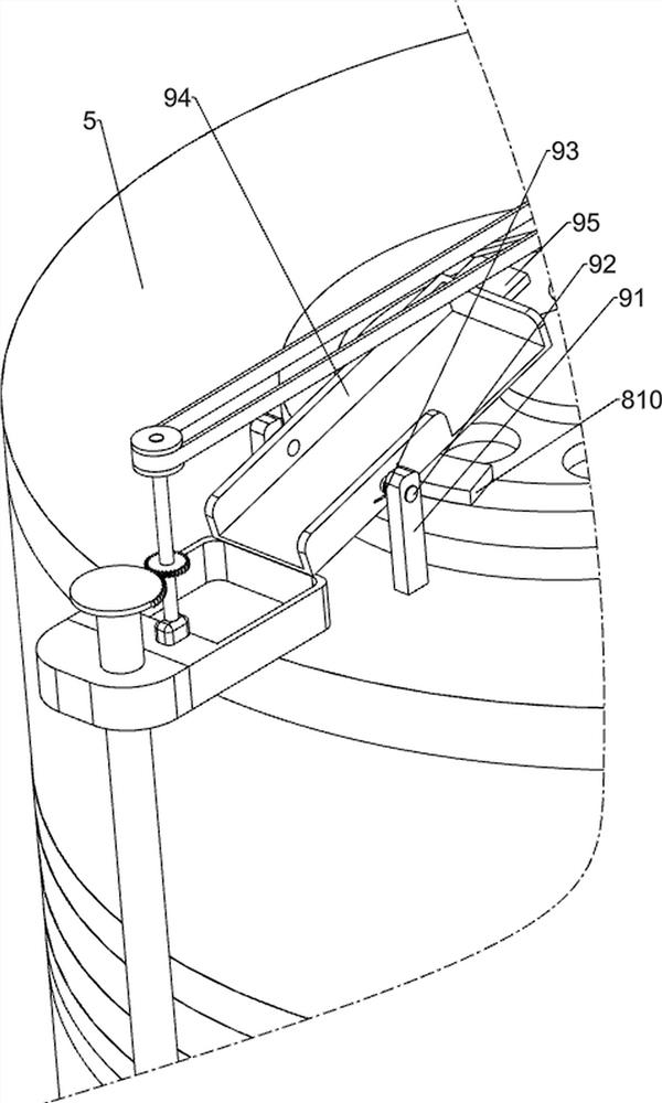
[0029] A cutting fluid recovery and reuse device for high-grade CNC machine tools, such as Figure 1-8 As shown, it includes a first fixed plate 1, a collection ring plate 2, a leakage plate 3, a first filter plate 4, a ring plate cover 5, an oil inlet mechanism 6 and a magnetic suction mechanism 7, and the top of the first fixed plate 1 is welded The collection ring plate 2 is arranged in the way, the top of the collection ring plate 2 is provided with the drain plate 3 by welding, the top of the drain plate 3 is provided with the first filter plate 4 by welding, and the top of the first filter plate 4 is set by welding There is a ring plate cover 5, the top of the ring plate cover 5 is provided with an oil inlet mechanism 6 that can absorb cutting fluid, and a magnetic attraction that can remove extremely fine iron filings in the cutting fluid is connected between the collecting ring plate 2 and the first fixed plate 1 Mechanism 7, the rear side and the top of the ring plate...


PUM


Abstract

The invention relates to a recycling device, and especially relates to a cutting fluid recycling device for a high-grade numerical control machine tool. The technical problem of the invention is to provide the cutting fluid recycling device for the high-grade numerical control machine tool can quickly remove scrap iron in cutting fluid. The cutting fluid recycling device for the high-grade numerical control machine tool comprises a first fixing plate, a collecting annular plate, a leakage plate, a first filtering plate, an annular plate cover, an oil inlet mechanism and a magnetic attraction mechanism, the collecting annular plate is arranged at the top of the first fixing plate, the leakage plate is arranged at the top of the collecting annular plate, the first filtering plate is arranged at the top of the leakage plate, and the annular plate cover is arranged at the top of the first filtering plate. The oil inlet mechanism is arranged at the top of the annular plate cover, and the magnetic attraction mechanism is connected between the collecting annular plate and the first fixing plate. Under the magnetic attraction action of a powerful magnet, tiny scrap iron in the cutting fluid can be attracted out, so that the cleaning effect is better.

Description

technical field [0001] The invention relates to a recycling device, in particular to a cutting fluid recycling device for high-grade numerically controlled machine tools. Background technique [0002] Cutting fluid is an industrial liquid used in metal cutting and grinding to cool and lubricate cutting tools and workpieces. It is often used in various high-end CNC machine tools. It has good cooling, cleaning, antirust, etc. It has the characteristics of non-toxic, odorless, non-corrosive to human body, non-corrosive to equipment, and non-polluting to the environment. It can be recycled after removing impurities such as iron filings in the cutting fluid after use, and removes the impurities in the cutting fluid. For iron filings, the powerful magnets are manually carried into the cutting fluid pool, and the iron filings can be absorbed under the action of the powerful magnets. It is inconvenient to manually move in the cutting fluid pool, which makes it difficult to remove ir...

Claims


Application Information

Patent Timeline
Patent Type & Authority Applications(China)
IPC IPC(8): B03C1/30B23Q11/10
CPCB03C1/30B23Q11/1069
Inventor 刘惠强
Owner 东莞市技师学院
Learn More