Intelligent rapid drying seamless steel pipe outer wall paint spraying device
A technology for rapid drying and seamless steel pipe, applied in the directions of drying, dryer, drying gas arrangement, etc., can solve the problems of wasting energy and time, the spray paint on the outer wall of the seamless steel pipe is not completely dry, and the drying speed is slow, etc. Achieve the effect of fast drying speed, good energy saving effect and high thermal efficiency
- Summary
- Abstract
- Description
- Claims
- Application Information
AI Technical Summary
Problems solved by technology
Method used
Image
Examples
Embodiment 1
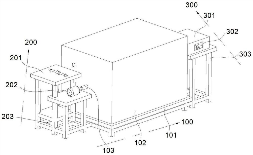
[0031] Refer figure 1 with figure 2 A intelligent quick drying seamless steel tube outer wall painting device, including, a table assembly 100, a table assembly 100 including a bottom plate 101, a casing 102, and a rotating shaft 103, and the top of the bottom plate 101 fixes a box body 102, a box body 102 is composed of two internal and external steel plates, there is a certain void in the middle, and the rotation shaft 103 is disposed within the casing 102; the heating assembly 200, the heating assembly 200 is disposed on the cabinet 102, including the first workstation 201, motor 202 And the fan 203, the motor 202 is fixed below the top of the first table 201; The humidity detecting box 301 is connected, and there is a row network 302 on the front and rear sides of the humidity detection box 301, and the wet detection box 301 is fixedly connected to the four table 303.
[0032] Specifically, the main body structure of the present invention includes a table assembly 100, a heati...
Embodiment 2
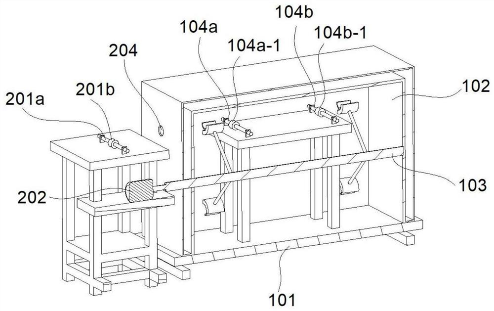
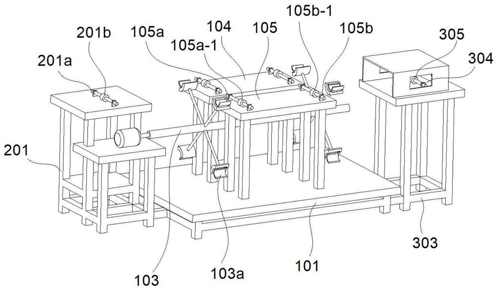
[0037] Refer Figure 2 ~ 6 This embodiment is different from the first embodiment. The output shaft of the motor 202 is fixedly connected to the rotating shaft 103 through the coupling, and the rotation shaft 103 is remote from the motor 202 through the casing 102 and extended to the box 102. The inner, the rotation shaft 103 extends one end of the inside of the casing 102 and is rotatably coupled to one side of the inner wall of the casing 102, and the rotation shaft 103 is located between the 2ter table 104 and the 3 table 105. The two sets of link members 103a are fixed to the rotating shaft 103, and the two sets of link members 103a are located on both sides of the second table 104, each set of link members 103a, respectively, four link members 103a, and rotate The shaft 103 is circularly distributed. The first end of the line No. 1 is move away from the rotating shaft 103 is slidably connected to the first slider 103b-1, the upper arcuate surface of the 1 slider 103b-1 is a ga...
Embodiment 3
[0048] Refer Figure 2 ~ 6 This embodiment is different from the above embodiment is: The other side of the casing 102 has a through hole 204, and the No. 1 through hole 204 penetrates the inside and outside of the casing 102, one side of the No. 1 through hole 204 and is located in the casing. There is a table 201, and there is a wind opening 205 after the rear of the box 102, and the air opening 205 is formed through the inner steel plate of the box 102, and the front side of the box 102 is opened. 206, No. 2 out The air inlet 206 only penetrates the outer steel sheet of the casing 102, wherein the case 102 is fixedly connected to the front side, and a temperature sensor 109 is provided in the casing 102.
[0049] The first end of the No. 1 workbench is fixedly connected with one electric drum 201a, and the first electric drum 201a is fixed, rotary motion, the No. 1 electric drum 201a has a steel pipe fixture 201b, and the first electric drum 201a is below. A motor 202 is fixed t...
PUM
 Abstract
Description
Claims
Application Information
 - R&D
- Intellectual Property
- Life Sciences
- Materials
- Tech Scout
- Unparalleled Data Quality
- Higher Quality Content
- 60% Fewer Hallucinations
Browse by: Latest US Patents, China's latest patents, Technical Efficacy Thesaurus, Application Domain, Technology Topic, Popular Technical Reports.
© 2025 PatSnap. All rights reserved.Legal|Privacy policy|Modern Slavery Act Transparency Statement|Sitemap|About US| Contact US: help@patsnap.com


