Positioning device facilitating stamping of chain wheel
A positioning device and sprocket technology, applied in the direction of positioning device, feeding device, storage device, etc., can solve the problems of inability to realize multi-group processing, inconvenient multi-group continuous stamping at the inner end, inconvenient stamping production positioning, etc., to achieve Convenient symmetrical processing, improved motion performance, and improved efficiency
- Summary
- Abstract
- Description
- Claims
- Application Information
AI Technical Summary
Problems solved by technology
Method used
Image

Examples
Embodiment Construction
[0031] The following will clearly and completely describe the technical solutions in the embodiments of the present invention with reference to the accompanying drawings in the embodiments of the present invention. Obviously, the described embodiments are only some, not all, embodiments of the present invention. Based on the embodiments of the present invention, all other embodiments obtained by persons of ordinary skill in the art without making creative efforts belong to the protection scope of the present invention.
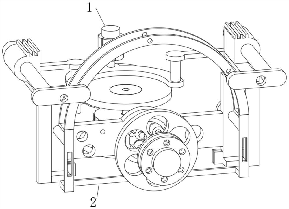
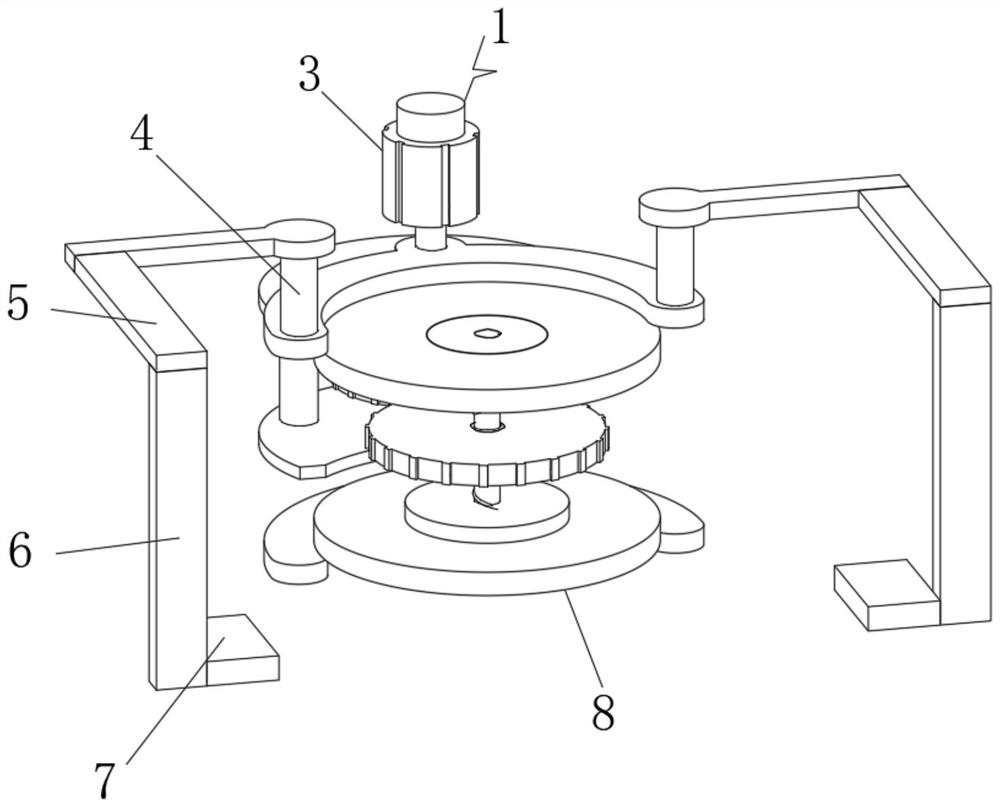
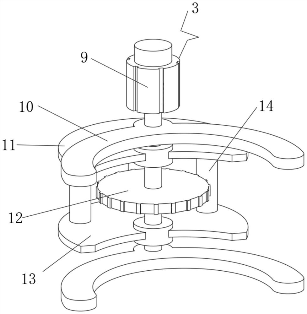
[0032] see Figure 1-7 , the present invention provides a technical solution: a convenient sprocket punching and positioning device, including a driving device 1, the front end of the driving device 1 is slidably connected with an operating device 2, and by installing the driving device 1, the inner end of the driving device 1 is driven , can realize the connection of the processed parts, facilitate the positioning and installation of the processed parts, real...
PUM
 Abstract
Description
Claims
Application Information