Motor pin shearing and gear press-fitting device and method

A press-fitting device and pin technology, which is applied to other manufacturing equipment/tools, manufacturing tools, etc., can solve the problems of inability to guarantee pin height consistency, unusable pins, low work efficiency, etc., and achieve pin height consistency , the pass rate improvement, the effect of high work efficiency

Pending Publication Date: 2021-11-26
NANJING AOLIAN AE&EA
View PDF0 Cites 1 Cited by
  • Summary
  • Abstract
  • Description
  • Claims
  • Application Information

AI Technical Summary

Problems solved by technology

In the prior art, the motor pins are cut manually. Manually cutting the motor pins cannot guarantee the consistency of the pin height after cutting, and it is time-consuming and laborious. It is also prone to pin shearing due to improper operation. The problem that the motor is scrapped due to being too low to use
[0004] On the other hand, in the prior art, the assembly of the motor shaft gear and the motor shear pins are carried out step by step, and the motor after the pins are manually cut is sent to the gear press-fitting device for gear press-fitting, and the work efficiency is low; and, The precision of the existing motor gear press-fitting device is low and the motor will be damaged during the press-fitting process

Method used


Image

  • Motor pin shearing and gear press-fitting device and method
  • Motor pin shearing and gear press-fitting device and method
  • Motor pin shearing and gear press-fitting device and method

Examples


Embodiment approach 1

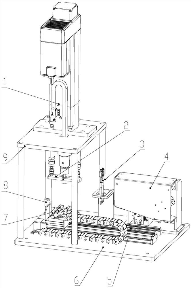
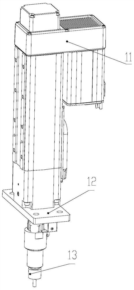
[0040] refer to Figure 1-11 , this embodiment provides a motor pin cutting and gear pressing device, including a servo pressing mechanism 1, a gear placement mechanism 2, a pin height detection mechanism 3, a pin cutting mechanism 4, a transfer mechanism 5, Working platform 6, motor clamping mechanism 7, motor sensor 8 and supporting platform 9.

[0041] The transfer mechanism 5 is installed on the working platform 6, and is used to transfer the motor in the motor clamping mechanism 7 to perform gear press-fitting, pin detection and pin cutting processes. The motor clamping mechanism 7 is provided with a jig for motor positioning 73;

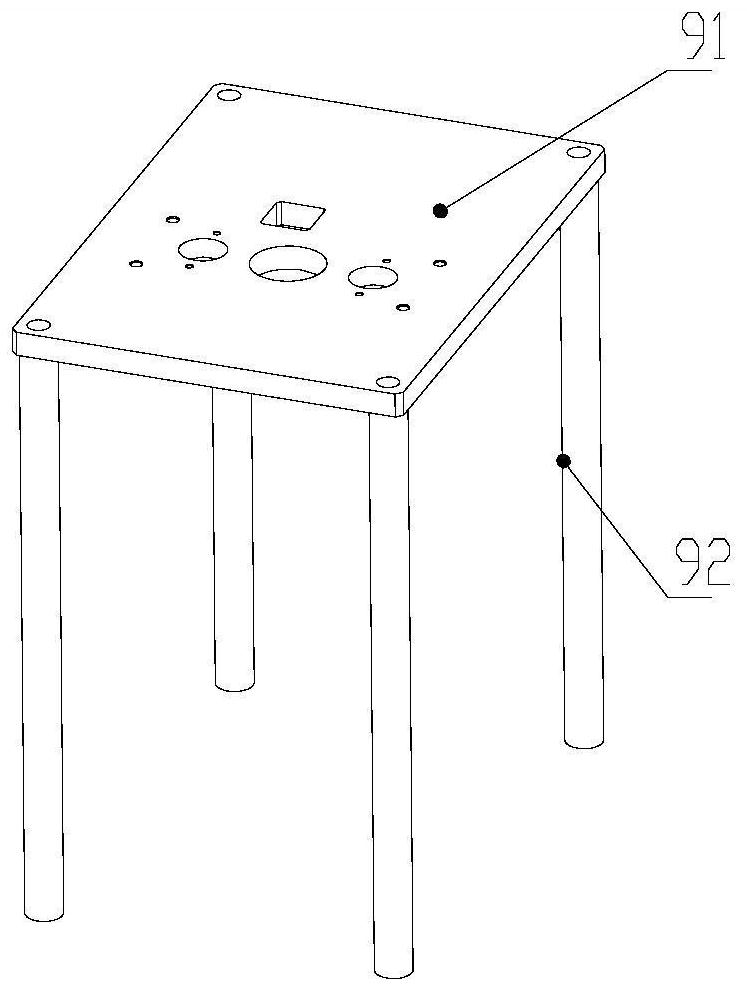
[0042]The support platform 9 is set on the working platform 6, and is used for installing the servo press-fit mechanism 1, the gear placement mechanism 2, the pin height detection mechanism 3 and the motor sensor 8;

[0043] The gear placement mechanism 2 is arranged below the support platform 9 and facing the motor positioning jig 73, the se...

Embodiment approach 2

[0055] refer to Figure 1 to Figure 11 , the present embodiment provides a motor gear press-fitting and pin cutting method used in embodiment 1, comprising the following steps:

[0056] The first step is to align the motor groove 103 with the limit block in the limit groove 74 and place it in the motor positioning jig 73; the motor sensor 8 detects the motor 10; the air claw 72 is activated to clamp and fix the motor 10 on the motor clamp Hold mechanism 7 on. At this time, the position of the transfer plate 51 where the motor 10 is located is the first station;

[0057] In the second step, the electric push cylinder 54 drives the transfer plate 51 to drive the motor clamping mechanism 7 to enter the pin height detection mechanism 3, the motor shaft of the motor 10 is located in the middle of the two displacement sensors 33, and the measuring heads of the two displacement sensors 33 Stretch out to measure the height of the motor pins and then retract;

[0058] In the third s...


PUM


Abstract

The invention discloses a motor pin shearing and gear press-fitting device and method. The motor pin shearing and gear press-fitting device comprises a servo press-fitting mechanism, a gear placing mechanism, a pin height detection mechanism, a pin shearing mechanism, a transfer mechanism, a working platform, a motor clamping mechanism, a motor sensor and a supporting platform, wherein the transfer mechanism is installed on the working platform and used for conveying a motor clamped in the motor clamping mechanism to carry out gear press-fitting, pin detection and pin shearing procedures. According to the invention, the pin shearing and gear press-fitting work of the motor can be completed in one device, the working efficiency is high, the pin heights are consistent, and the percent of pass is greatly improved.

Description

technical field [0001] The invention relates to the technical field of motor pin cutting and gear pressing, in particular to a motor pin cutting and gear pressing device and method. Background technique [0002] Motors are essential power components in various actuators of automobiles. When the motor is energized, the output shaft of the motor rotates, and the gears on the shaft drive other components to rotate through meshing, thereby outputting power. [0003] When the motor leaves the factory, the motor pins are generally set longer to facilitate the user to perform secondary cutting according to needs. In the prior art, the motor pins are cut manually. Manually cutting the motor pins cannot guarantee the consistency of the pin height after cutting, and it is time-consuming and laborious. It is also prone to pin shearing due to improper operation. If it is too low, it cannot be used, causing the motor to be scrapped. [0004] On the other hand, in the prior art, the as...

Claims


Application Information

Patent Timeline
Patent Type & Authority Applications(China)
IPC IPC(8): B23P15/00B23P23/04
CPCB23P15/00B23P23/04
Inventor 张志亮鲍海洋程卉
Owner NANJING AOLIAN AE&EA
Why Eureka
Try Eureka