
Transfer printing plate and transfer printing device

A technology of pad printing device and pad printing plate, which is applied in the direction of printing device, printing, printing plate, etc., can solve the problems of insufficient line width, insufficient thickness, difficult to remove, etc., to avoid abnormal material injection, improve production efficiency, and avoid a large number of The effect of scrapping or requiring rework

Active Publication Date: 2021-11-26
TCL CHINA STAR OPTOELECTRONICS TECH CO LTD
View PDF8 Cites 0 Cited by
  • Summary
  • Abstract
  • Description
  • Claims
  • Application Information

AI Technical Summary

Problems solved by technology

However, when it is used for a long time, it will cause the silver paste residue to harden in the groove on the board body, reduce the depth of the groove, and it is difficult to remove, so that the circuit printed to the side of the display screen will be disconnected and the line width will be insufficient. , uneven line width, or insufficient thickness
[0005] Therefore, in the existing pad printing technology, due to the residual slurry in the grooves on the plate body of the pad printing plate, the circuit printed on the substrate is disconnected, the line width is insufficient, the line width is uneven, or the thickness Issues such as deficiencies need to be resolved

Method used


Image

  • Transfer printing plate and transfer printing device
  • Transfer printing plate and transfer printing device
  • Transfer printing plate and transfer printing device

Examples


Embodiment Construction

[0021] The pad printing plate and the pad printing device provided by the embodiments of the present invention will be described in detail below with reference to the accompanying drawings. Apparently, the described embodiments are only some of the embodiments of the present invention, but not all of them. Based on the embodiments of the present invention, all other embodiments obtained by persons of ordinary skill in the art without making creative efforts belong to the protection scope of the present invention.

[0022] The following descriptions of the various embodiments refer to the accompanying drawings to illustrate specific embodiments that the present application can be used to implement. The directional terms mentioned in this application, such as [top], [bottom], [front], [back], [left], [right], [inside], [outside], [side], etc., are for reference only The orientation of the attached schema. Therefore, the directional terms used are used to illustrate and underst...


PUM


Abstract

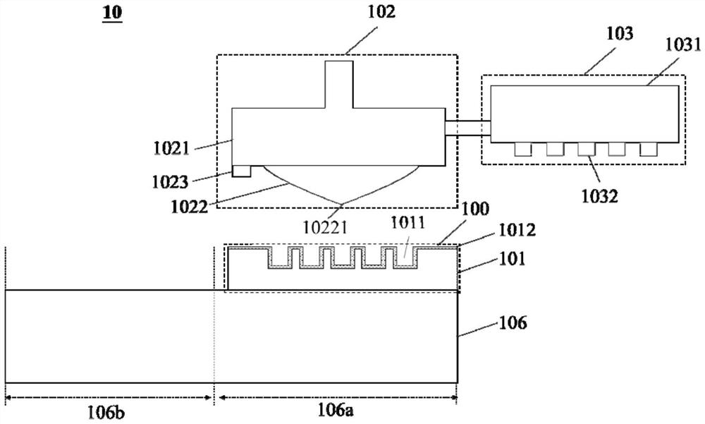
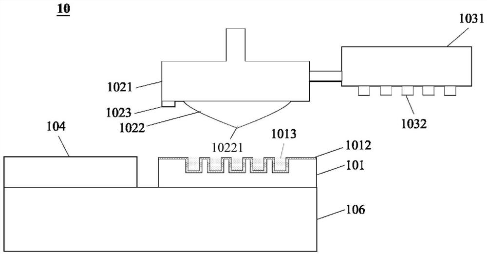
The invention provides a transfer printing plate and a transfer printing device. The transfer printing device comprises a printing platform, the transfer printing plate, a transfer printing module and an injection module. The transfer printing plate is arranged on the printing platform, the transfer printing plate comprises a plate body, and at least one groove is defined in the surface of the plate body; the transfer printing module is arranged above the printing platform; the injection module is arranged at one side of the transfer printing module; and the surface of the plate body and the inner surface in the at least one groove are coated with a coating, and the coating has hydrophobic and oleophobic characteristics.

Description

[0001] The invention relates to the technical field of pad printing, in particular to a pad printing plate and a pad printing device, which can be applied to pad printing of side circuits of display devices. Background technique [0002] Pad printing refers to pad printing graphics or text on the surface of a substrate, such as an instrument, a part, or any object. [0003] This pad printing technology is also used in the manufacturing of display devices. For example, in order to realize large outdoor advertising screens, central control large screens in command centers, or high-definition display large screens in movie theaters, it is usually necessary to splice multiple small The display screen forms a large display screen. A key technology in the splicing process is the line transfer process, which realizes side bonding by printing lines on the side of the display screen to reduce the frame gap of the front display area of ​​the display screen, thereby achieving a better la...

Claims


Application Information

Patent Timeline
Patent Type & Authority Applications(China)
IPC IPC(8): B41F17/00B41F31/08B41N1/00
CPCB41F17/001B41F31/08B41N1/00B41P2217/10B41P2217/50Y02E10/50
Inventor 程旷男
Owner TCL CHINA STAR OPTOELECTRONICS TECH CO LTD
Learn More