Powder filling machine

A filling machine and powder technology, applied in the direction of solid materials, packaging, packaging items, etc., can solve the problem of slow filling speed, and achieve the effect of improving fluidity, facilitating internal cleaning, and improving filling speed.

Pending Publication Date: 2021-11-26
ZHENGZHOU TONGDING MASCH EQUIP CO LTD
View PDF7 Cites 0 Cited by
  • Summary
  • Abstract
  • Description
  • Claims
  • Application Information

AI Technical Summary

Problems solved by technology

[0004] The purpose of the present invention is to provide a powder filling machine to solve the technical problem of slow filling speed of screw packaging machines in the prior art

Method used


Image

  • Powder filling machine
  • Powder filling machine
  • Powder filling machine

Examples


specific Embodiment 1

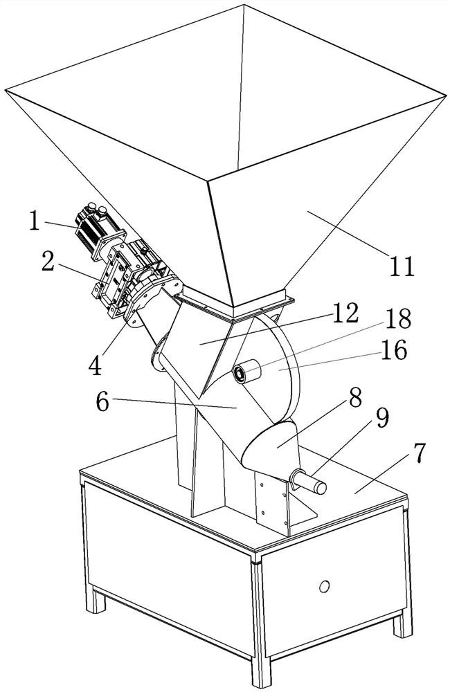
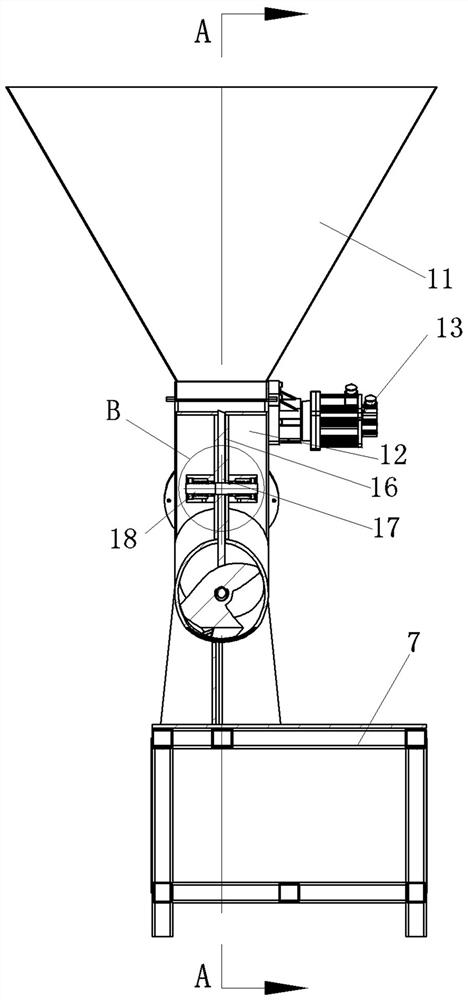
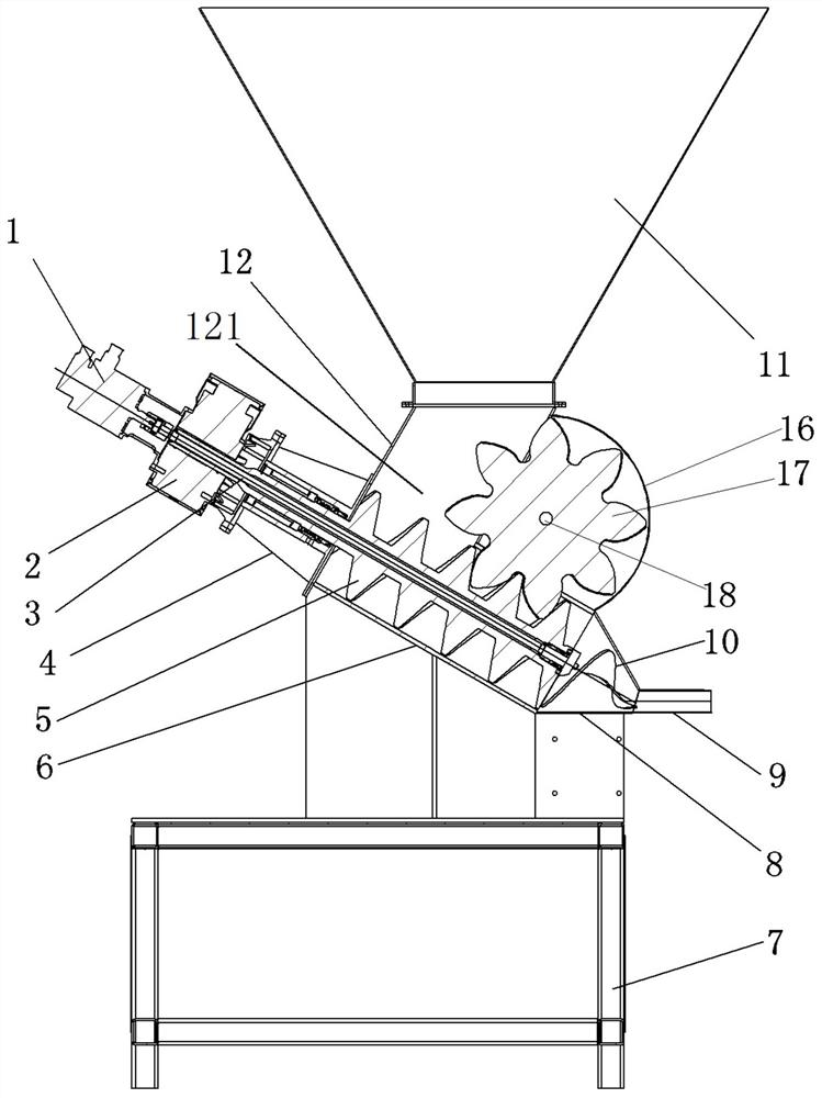
[0048] Such as Figure 1 to Figure 7 As shown, in the powder filling machine provided in this embodiment, a filling pipe 9 is provided at the outlet of the front end of the conveying cylinder 6 for filling powder into the valve pocket, and a main screw 5 is installed in the conveying cylinder 6, The main screw 5 is used to convey the powder forward, and the corresponding main screw 5 is equipped with a stopper worm gear 17. The stopper worm 17 cooperates with the main screw 5 in a corresponding spiral, so that the main screw 5 drives the stopper worm 17 to rotate, and the stopper worm 17 The worm gear teeth extend into the spiral groove of the main screw 5 to block the powder in the spiral groove, prevent the powder from rotating with the spiral groove, ensure that the main screw can effectively push the powder forward, and then build up the filling pressure.

[0049] In addition, since the inner diameter of the filling pipe 9 is smaller than the inner diameter of the conveyin...

specific Embodiment 2

[0070] Its difference with implementation: 1 mainly lies in: in embodiment 1, the agitating vane of boiling head is equal-pitch conical helical structure. In this embodiment, the structure of the boiling head is as Figure 8 As shown, the boiling head 10 also includes a base 101, the base 101 is used for fixed assembly with the front end of the inner drive shaft, and the stirring blade 102 is installed on the base 101, the stirring blade 102 is a spiral blade, and the spiral blade follows a logarithmic spiral The spiral blade extends along the circumferential direction of the boiling head gradually from the back to the front, and the outer diameter of the spiral blade gradually becomes smaller from the back to the front to correspond to the inner surface of the conical powder gathering cone.

[0071] There are two helical blades arranged symmetrically with respect to the central axis of the boiling head, and there is a gap at the side of the central axis of the boiling head co...

specific Embodiment 3

[0074] The main difference between it and Embodiment 2 is that in Embodiment 2, the center of the boiling head is hollow to form a hollow boiling head structure. In this embodiment, for the two-leaf helical blade, such as Figure 9 As shown, the boiling head 10 is provided with a central column 103 at the position of the central axis of the boiling head. The central column 103 extends along the front and rear directions. The central column 103 is a cone that gradually decreases from the back to the front. On the outer peripheral surface of the column 103, in this way, when a high-speed rotation is required, the central column 103 can effectively enhance the overall strength of the boiling head 10, and the tendency of rotation flutter is small.

[0075] In other embodiments, the central column can also be a cylindrical structure, which can also enhance the strength of the boiling head.

[0076] Here, the central column is arranged on the boiling head, so that the boiling head ...


PUM


Abstract

The invention relates to a powder filling machine. The powder filling machine comprises a conveying barrel and a spiral conveying groove, wherein a main screw rod is coaxially and rotatably assembled in the conveying barrel, a worm gear shell is arranged on the conveying barrel, an inner cavity of the worm gear shell communicates with an inner cavity of the conveying barrel, a material blocking worm gear is assembled in the worm gear shell in a supporting mode, and the central axis of the material blocking worm gear is perpendicular to the central axis of the main screw rod; the material blocking worm gear is in corresponding spiral fit with the main screw rod, so that the main screw rod drives the material blocking worm gear to rotate; and in the front-back direction, the meshing position of worm gear teeth of the material blocking worm gear and the main screw rod is located in front of a feeding cavity, so that the worm gear teeth extending into a spiral groove of the main screw rod block powder in the spiral groove to rotate along with the main screw rod, the filling pressure is established, forward movement of the powder can be accelerated, the filling speed is increased, high-speed dense filling of a valve bag with the powder can be achieved without mixing of high-pressure air, dust generated when the valve bag is filled with the powder is reduced, and the purposes of efficient filling and environmental protection are achieved.

Description

technical field [0001] The invention relates to a powder filling machine. Background technique [0002] At present, the packaging machines for powder valve pocket filling in the dry powder mortar industry on the market include air-floating, centrifugal, and screw-type structures. Compressed air needs to be mixed in to improve the flow performance of dry powder. The added compressed air can increase the filling speed of the dry powder, but the powder will enter the valve bag together with the compressed air. After the filling is completed, the compressed air in the bag needs to be discharged. In fact, the compressed air in the bag is difficult to discharge. As a result, the compactness of the powder in the bag cannot meet the needs of users, and the discharged compressed air will carry dust, which increases the load on the dust removal equipment. [0003] The screw-type packaging machine adopts the screw to convey the powder, such as the utility model patent with the author...

Claims


Application Information

Patent Timeline
Patent Type & Authority Applications(China)
IPC IPC(8): B65B1/28B65B1/12B65B1/06B65B1/04
CPCB65B1/28B65B1/12B65B1/06B65B1/04
Inventor 董青山毛君豪丁岩刘广磊赵文龙
Owner ZHENGZHOU TONGDING MASCH EQUIP CO LTD
Why Eureka
Try Eureka