Defoaming heat-resistant conveying equipment for glass production and manufacturing

A conveying equipment and heat-resistant technology, applied in the field of glass production, can solve the problems of heat accumulation, poor heat-resistant effect of the bearing device, and inability to effectively release it, and achieve the effect of increasing the heat dissipation effect, increasing the cleaning effect, and increasing the effect of auxiliary air flow.

Pending Publication Date: 2021-11-26
徐州市威固特种玻璃有限公司
View PDF4 Cites 0 Cited by
  • Summary
  • Abstract
  • Description
  • Claims
  • Application Information

AI Technical Summary

Problems solved by technology

[0005] In order to solve the above technical problems, the present invention provides a defoaming and heat-resistant conveying equipment for glass production to solve the need to pressurize the melted liquid glass in glass production and to anneal and cool the glass, but the existing After a long-term use of the carrying device, heat will accumulate and cannot be released effectively, resulting in the problem of poor heat resistance of the carrying device

Method used


Image

  • Defoaming heat-resistant conveying equipment for glass production and manufacturing
  • Defoaming heat-resistant conveying equipment for glass production and manufacturing
  • Defoaming heat-resistant conveying equipment for glass production and manufacturing

Examples


Embodiment

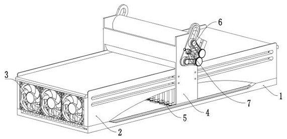
[0028] Example: as attached figure 1 to attach Figure 10 As shown: the present invention provides a defoaming and heat-resistant conveying equipment for glass production and manufacturing, including a base structure 1; 2 is equipped with a heat dissipation structure 3; the heat dissipation structure 3 includes: a heat dissipation frame 301, the heat dissipation frame 301 is a sheet structure, the heat dissipation frame 301 is arranged in an array, and an arc-shaped groove is opened at the bottom, and the arc-shaped shape of the heat dissipation frame 301 The groove matches the arc groove at the carrier frame 201, and the cooling frame 301 is fixed in the carrier frame 201. The cooling frame 301 of the carrier frame 201 is conducive to the heat transfer between the cooling frame 301 and the carrier frame 201. The cooling rack 301 arranged in an array increases the heat dissipation effect of the cooling rack 301; the cooling fan 302, the cooling fan 302 is installed at the lef...

no. 2 example

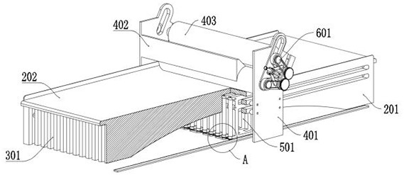
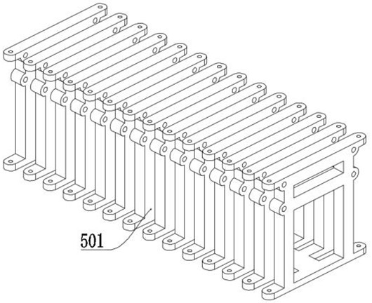
[0033] The second embodiment: the installation structure 4, the installation structure 4 is slidably installed on the bearing device 2, and the bottom of the installation structure 4 is fixed with a cleaning structure 5; wherein, the cleaning structure 5 includes: a bottom carriage 501, and the bottom carriage 501 is a frame structure , the bottom carriages 501 are arranged in an array structure, and the bottom carriages 501 arranged in an array are connected and fixed at the bottom, and the distance between each group of bottom carriages 501 matches the heat dissipation frame 301, and through the bottom carriages 501 that match the heat dissipation frame 301, Realize that the frame body of the bottom carriage 501 can slide on the bottom of the heat sink 301, the bottom carriage 501 is fixed on the installation plate 401, and realize the drive when the installation plate 401 moves through the bottom carriage 501 fixed on the installation plate 401. The bottom carriage 501 slide...

no. 3 example

[0036] The third embodiment: the transmission assembly 6, the transmission assembly 6 is arranged on the front and rear end outer walls of the cleaning structure 5, and the position of the transmission assembly 6 is provided with a sliding structure 7 at the same time.

[0037] Wherein, the transmission assembly 6 includes: a sliding plate 604, the sliding plate 604 is a round structure, the sliding plate 604 is slidably installed on the mounting plate 401, and by sliding the sliding plate 604 installed on the mounting plate 401, it is beneficial to press the pressure wheel 403 Convenience during adjustment; external gear 601, two groups of external gears 601 are arranged altogether, two groups of external gears 601 are rotatably installed on the outermost end of sliding plate 604, gear teeth are arranged on the outer wall of external gear 601, two groups of external gears 601 are mutual The meshing structure, by installing the external gear 601 on the outermost end of the slid...


PUM


Abstract

The invention provides defoaming heat-resistant conveying equipment for glass production and manufacturing, relates to the technical field of glass production, and solves the problems that when glass is annealed and cooled, heat is accumulated and cannot be effectively released after an existing bearing device is used for a long time, and the heat-resistant effect of the bearing device is poor. The defoaming heat-resistant conveying equipment comprises a base structure. The base structure is placed on the ground, a bearing device is arranged at the upper end of the base structure, and a heat dissipation structure is installed in the bearing device; the heat dissipation structure comprises heat dissipation frames, the heat dissipation frames are of a sheet-shaped structure and are arranged in an array mode, arc-shaped grooves are formed in the bottom ends of the heat dissipation frames, the arc-shaped grooves of the heat dissipation frames are matched with the arc-shaped grooves in the bearing frame, the heat dissipation frames are fixed in the bearing frame, and the heat dissipation frames of the bearing frame are beneficial to heat transfer between the heat dissipation frames and the bearing frame; the heat dissipation effect of the heat dissipation frame is improved by arranging the heat dissipation frame arranged in the sheet-shaped array mode.

Description

technical field [0001] The invention belongs to the technical field of glass production, and more specifically relates to a defoaming and heat-resistant conveying equipment for glass production. Background technique [0002] Glass is a material that is widely used in modern times. Glass is an amorphous inorganic non-metallic material. Generally, a variety of inorganic minerals are used as the main raw material. Glass is a hard and brittle transparent object. Quartz sand, limestone, soda ash, etc. are generally used. After mixing, it is made by melting at high temperature, forming and cooling. [0003] Based on the above, in the production of glass, the melted liquid glass needs to be pressurized, and the glass needs to be annealed and cooled. However, after the existing carrying device is used for a long time, heat will accumulate and cannot be effectively released, resulting in the heat resistance of the carrying device. bad question. [0004] Therefore, in view of this, ...

Claims


Application Information

Patent Timeline
Patent Type & Authority Applications(China)
IPC IPC(8): C03B35/00
CPCC03B35/00
Inventor 葛祖根陆晔宋庆
Owner 徐州市威固特种玻璃有限公司
Why Eureka
Try Eureka