A heat treatment quenching device for plates

A quenching device and plate technology, applied in the field of quenching, can solve the problems of easy leakage of heat, low efficiency and waste gas

Active Publication Date: 2022-05-17
南通恒泰热处理有限公司
View PDF8 Cites 2 Cited by
  • Summary
  • Abstract
  • Description
  • Claims
  • Application Information

AI Technical Summary

Problems solved by technology

[0005] Aiming at the deficiencies of the prior art, the present invention provides a heat treatment and quenching device for plates, which solves the problems of low efficiency of traditional quenching equipment and easy leakage of exhaust gas and heat

Method used


Image

  • A heat treatment quenching device for plates
  • A heat treatment quenching device for plates
  • A heat treatment quenching device for plates

Examples


Embodiment Construction

[0033] The following will clearly and completely describe the technical solutions in the embodiments of the present invention with reference to the accompanying drawings in the embodiments of the present invention. Obviously, the described embodiments are only some, not all, embodiments of the present invention. Based on the embodiments of the present invention, all other embodiments obtained by persons of ordinary skill in the art without making creative efforts belong to the protection scope of the present invention.

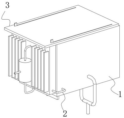
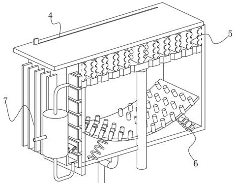
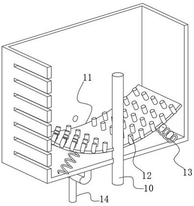
[0034] see Figure 1-7, the present invention provides a technical solution: a heat treatment and quenching device for plates, including a body 1, the front and back of the body 1 are fixedly connected with a U-shaped tube 2, and the top of the U-shaped tube 2 is provided with a cover plate 3, the cover plate 3 The lower surface of the lower surface is slidingly connected with the upper surface of the body 1, a chute 4 is opened in the wall of the cover plate ...


PUM


Abstract

The invention discloses a heat treatment and quenching device for plates, which comprises a machine body. U-shaped tubes are fixedly connected to the front and back of the machine body. A cover plate is arranged on the top of the U-shaped tube. The upper surface of the cover plate is slidably connected, a chute is opened in the wall of the cover plate, and a clamping device is provided at the bottom of the chute. The invention relates to the field of quenching technology. The heat treatment and quenching device is used for the plate. By setting the adjustment device, when the plate is clamped inside the clamping device, the movable rod moves downward, and the plate is pulled into the inside of the machine body. Under the extrusion of the bushing plate, the curved plate bends The arc decreases, the pin is inserted into the inside of the leak plate, and the compression spring squeezes and shrinks. At this time, the metal debris blocking the inside of the leak plate will be pushed out from the inside of the leak plate, and the debris remains on the upper surface or bottom area of ​​the arc plate. Under the impact of the water flow inside the cooling device, the debris is finally discharged from the slag discharge pipe, which solves the problem that the inside of the traditional quenching equipment is easily blocked by metal debris.

Description

technical field [0001] The invention relates to the technical field of quenching, in particular to a heat treatment quenching device for plates. Background technique [0002] The purpose of quenching is to transform supercooled austenite into martensite or bainite to obtain martensite or bainite structure, and then cooperate with tempering at different temperatures to greatly improve the rigidity, hardness and wear resistance of the steel. properties, fatigue strength and toughness, etc., so as to meet the different requirements of various mechanical parts and tools. Quenching can also be used to meet the special physical and chemical properties of some special steel materials such as ferromagnetism and corrosion resistance. [0003] When the traditional quenching equipment is in use, due to the open-air quenching, high-temperature steam and heat will be transferred outward at the moment of quenching, which is not conducive to the health of the operator. At the same time, w...

Claims


Application Information

Patent Timeline
Patent Type & Authority Patents(China)
IPC IPC(8): C21D9/00C21D1/64
CPCC21D9/0081C21D1/64Y02P10/20
Inventor 周顺全
Owner 南通恒泰热处理有限公司
Why Eureka
Try Eureka