Sunlight illumination system

A lighting system and sunlight technology, applied in the field of sunlight lighting systems, can solve the problems of high light energy utilization temperature of sunlight lighting equipment and cannot be used at night, and achieve the effects of low energy consumption cost, reduced damage, and ensured safe transportation.

Inactive Publication Date: 2021-11-26
HUBEI UNIV OF ARTS & SCI
View PDF0 Cites 0 Cited by
  • Summary
  • Abstract
  • Description
  • Claims
  • Application Information

AI Technical Summary

Problems solved by technology

[0004] The purpose of the present invention is to provide a sunlight lighting system, which solves the problems in the prior art that sunlight lighting equipment cannot be used at night and the temperature is too high in the process of light energy utilization

Method used


Image

  • Sunlight illumination system
  • Sunlight illumination system
  • Sunlight illumination system

Examples


Embodiment 1

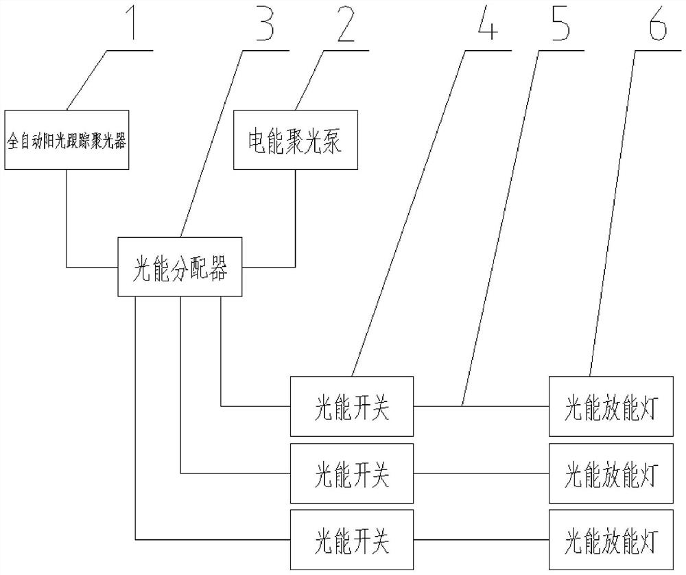
[0048] Such as figure 1 As shown, the present embodiment provides a sunlight lighting system, including a fully automatic sunlight tracking concentrator 1, an electric energy concentrator pump 2, a light energy distributor 3, a light energy switch 4, a liquid optical fiber line 5 and a sun lamp 6, automatically Both the sunlight tracking concentrator and the electric energy concentrator pump 2 are connected to the optical energy distributor 3 through the liquid optical fiber line 5, and the optical energy distributor 3 is connected to the solar lamp 6 through the liquid optical fiber line 5, and the solar lamp 6 is connected to the optical energy distributor 3 A light energy switch 4 is connected between them, a vacuum light guide tube 7 is provided at the output end of the automatic sunlight tracking concentrator 1 and the electric energy concentrator pump 2, and a vacuum light guide tube 7 is provided at the input end of the solar lamp 6 . The optical energy distributor 3 is...

Embodiment 2

[0104] Such as Figure 6 and Figure 7As shown, in this embodiment, on the basis of Embodiment 1, the shading sheet 41 is circular, with a round hole in the middle, and the shading sheet 41 is rotationally connected to the two opposite inner walls of the shading groove 6133, and the axis of the shading sheet 41 is connected to the threading hole. The axes are parallel, the driving device 42 is a servo motor, the output shaft of the driving device 42 is connected to the axis of the light-shielding sheet 41, the power supply of the driving device 42 is connected to the outside, and the light-shielding sheet 41 is equally divided into a dark area 411, a weak light area, etc. Area 412 and strong light area 413, the light-shielding sheet 41 itself is made of a transparent material plate with good light transmission, the dark area 411 is an opaque area, which is blocked by light-shielding paint, and the weak light area 412 is made of a coating with light filtering effect Coating, s...

Embodiment 3

[0109] Such as Figure 8 and Figure 9 As shown, the difference between this embodiment and Embodiment 2 is that the light-shielding sheet 41 is strip-shaped, the light-shielding groove 6133 runs through the radial direction of the optical fiber connector 613, the light-shielding sheet 41 is slidably arranged in the light-shielding groove 6133, and the driving device 42 is a small electric motor. Push-pull rod, the shading sheet 41 is divided into connecting area 414, dark area 411, weak light area 412 and strong light area 413 from top to bottom in turn, the dark area 411 has no light transmission, and the weak light area 412 is light-transmissive The ability is weak, the strong light area 413 has strong light transmission ability, the areas of the no light area 411, the weak light area 412 and the strong light area 413 are all larger than the radial cross-sectional area of ​​the threading hole, the connection between the output end of the driving device 42 and the light shie...


PUM


Abstract

The invention relates to the technical field of light energy gathering and releasing, and discloses a sunlight illumination system which comprises a full-automatic sunlight tracking condenser, an electric energy condensation pump, a light energy distributor, a light energy switch, liquid optical fiber lines and a sun lamp. The full-automatic sunlight tracking condenser and the electric energy condensation pump are both connected with the light energy distributor through liquid optical fiber lines, the light energy distributor is connected with the sunlamp through the liquid optical fiber lines, and the light energy switch is connected between the sun lamp and the light energy distributor. The output end of the full-automatic sunlight tracking condenser and the output end of the electric energy condensation pump are each provided with a vacuum light guide pipe, and the input end of the sun lamp is provided with a vacuum light guide pipe. The problems that sunlight lighting equipment cannot be used at night and the temperature is too high in the light energy utilization process in the prior art are solved.

Description

technical field [0001] The invention relates to the technical field of light energy concentration and release, in particular to a sunlight lighting system. Background technique [0002] Lighting is an old, eternal and young topic. Since the birth of human beings, in the long-term evolution process, they have been physiologically adapted to the irradiation of sunlight, a seven-color light source. In order to solve the problem of lighting in the dark night, human beings invented fire and lamps. Until modern times, electricity and electric lights were invented, which filled the dark night life of human beings with light. With the rapid development of modern technology, using electric energy as the energy supply of the light source has become the mainstream. The use of light spectrum is also advancing with each passing day. In order to save energy, modern society uses light energy of various spectra to constantly renovate. Some developments are going to extremes. Minor side ...

Claims


Application Information

Patent Timeline
Patent Type & Authority Applications(China)
IPC IPC(8): F21S11/00F21V8/00F21S9/03F21V23/04F21V23/00
CPCF21S11/005F21S11/007F21S9/032F21V23/04F21V23/00F21V2200/10Y02B20/72
Inventor 李梅杨传成
Owner HUBEI UNIV OF ARTS & SCI
Why Eureka
Try Eureka