

Hole wall side expansion rotary shearing device for drilling shear test and test method
A rotary shearing and shearing test technology, applied in the direction of using a stable shearing force to test the strength of materials, measuring devices, instruments, etc. Good mechanical properties, good mechanical properties and good mechanical properties
Active Publication Date: 2021-11-26
CHENGDU UNIVERSITY OF TECHNOLOGY
View PDF35 Cites 3 Cited by
- Summary
- Abstract
- Description
- Claims
- Application Information
AI Technical Summary
Problems solved by technology
The currently used drilling shear instrument is the Phicometre drilling shear instrument developed by APAGEO company in France, which needs to work in small diameter (60-66mm) drilling holes, but the common opening diameter in my country is above 90mm. To meet the working conditions of this foreign borehole shear instrument, additional holes ar
Method used
View moreImage
Smart ImageViewing Examples

Examples
 PUM
 Abstract
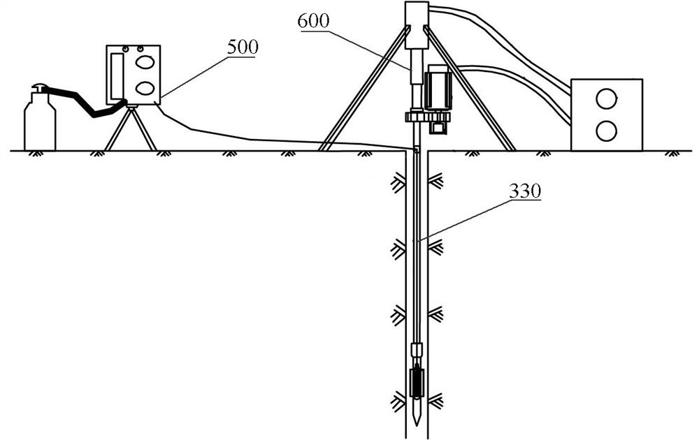
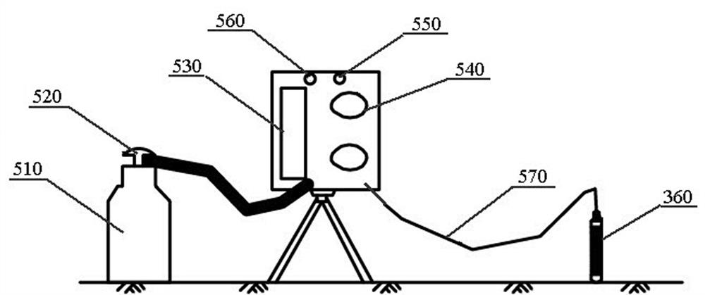
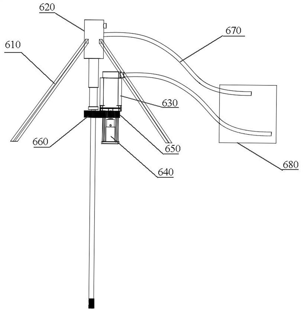
The invention discloses a hole wall side expansion rotary shearing device for a drilling shear test and a test method. The device comprises a mounting assembly for supporting the device, a lifting assembly and a shearing assembly; the lifting assembly is used for driving the shearing assembly to lift; the shearing assembly comprises a drill rod and a power device used for driving the drill rod to rotate and detachably connected with one end of the drill rod. The shearing unit comprises a first probe part and a second probe part arranged below the first probe part and connected with the first probe part; The device also comprises an expansion pipe which penetrates through the first probe part and extends into the second probe part; the expansion pipe is connected with a normal force providing device; a plurality of shearing sheets are arranged on the surface of the second probe part in the radial direction; the shearing sheets are arranged in an array, and the shearing sheets on the same straight line in the radial direction of the second probe part form a group; shearing sheets in two adjacent groups of shearing sheets are arranged in a staggered manner; opening positions distributed in the radial direction are arranged on the surface of the second probe part between two adjacent groups of shearing sheets. According to the invention, a lateral pressure test and a shear test can be realized, and the stress performance is good.
Description
technical field [0001] The invention relates to the technical field of drilling shear test devices, in particular to a hole wall lateral expansion rotary shearing device and a test method for drilling shear tests. Background technique [0002] The shear strength index of rock and soil is an important parameter to study the mechanical properties of soil and carry out engineering design. The determination of its indicators can adopt indoor test or in-situ test method. Traditional indoor tests include direct shear experiments, triaxial tests, etc., but the sample size of indoor tests is limited, and the representativeness is poor due to the disturbance and strict boundary conditions during transportation; and Although the in-situ test does not require sampling and can directly measure the shear strength index of rock and soil in the original stress environment, there are still many limiting factors. For example, the large-scale direct shear test on site has relatively accurate...
Claims
Login to View More Application Information
Patent Timeline
 IPC IPC(8): G01N3/24G01N3/02
Inventor冯文凯易小宇万柯姜杰李谦韩靖楠
OwnerCHENGDU UNIVERSITY OF TECHNOLOGY