Sample injection chip and method based on electrophoresis technology
A sample and sample injection technology, which is applied in the direction of material analysis, measuring devices, instruments, etc. by electromagnetic means, can solve the problems of affecting analysis, not applicable to the analysis of trace liquid, and poor repeatability, so as to reduce the structure complexity and The effect of reducing cost, reducing sample usage, and increasing analytical throughput
- Summary
- Abstract
- Description
- Claims
- Application Information
AI Technical Summary
Problems solved by technology
Method used
Image
Examples
Embodiment 1
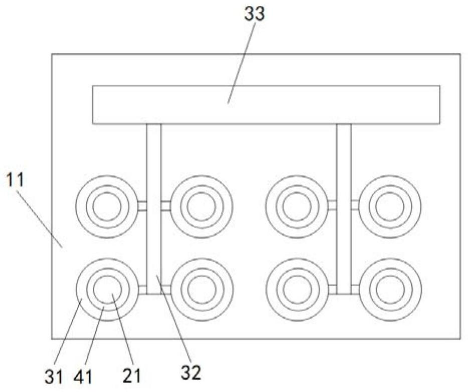
[0033] figure 1 The structure diagram of the sample injection chip based on electrophoresis technology in the embodiment of the present invention is given, as figure 1 As shown, the sample injection chip based on electrophoresis technology includes:
[0034] A base 11, the base 11 is made of an insulating material, such as glass;
[0035] A temporary storage module 21, the temporary storage module 21 is arranged on the base 11 for temporary storage of samples;
[0036] The electrodes 31 are arranged outside the temporary storage module 21 .
[0037] In order to improve the sampling efficiency, further, the electrode 31 is ring-shaped and arranged around the temporary storage module 21 .
[0038] In order to prevent the sample from contacting the electrodes during non-sampling time, further, the sample injection chip further includes:
[0039] A hydrophobic layer 41 , the hydrophobic layer 41 is disposed on the surface of the substrate between the temporary storage module 2...
Embodiment 2
[0051] An application example of the sample injection chip and sample injection method based on electrophoresis technology according to Embodiment 1 of the present invention.
[0052] In this application example, if figure 1 As shown, the substrate 11 is made of insulating glass, and the first connection part 32, the second connection part 33 and a plurality of ring electrodes 31 are formed on the surface of the substrate 11 by means of sputtering, etc., and the plurality of ring electrodes 31 are respectively located in the first connection part 32 two sides, and connected to the first connecting portion 32, a plurality of first connecting portions 32 connected to the second connecting portion 33;
[0053] The structure of the temporary storage module 21 is: a groove is processed on the substrate 11 inside the ring electrode 31, from bottom to top, the inner diameter of the groove becomes larger, and the inner diameter of the ring electrode 31 is greater than the maximum inne...
Embodiment 3
[0060] According to the application example of the sample injection chip in embodiment 1 of the present invention, the difference from embodiment 2 is:
[0061] 1. The structure of the temporary storage module is: a matrix-like hydrophilic layer is arranged on the surface of the substrate, electrodes are arranged on the hydrophilic layer, and a hydrophobic layer is arranged between the hydrophilic layer and the electrodes.
[0062] 2. The electrodes are non-circular, such as fan-shaped, arranged outside the hydrophobic layer, and connected to the first connection part.
PUM
 Abstract
Description
Claims
Application Information
 - R&D
- Intellectual Property
- Life Sciences
- Materials
- Tech Scout
- Unparalleled Data Quality
- Higher Quality Content
- 60% Fewer Hallucinations
Browse by: Latest US Patents, China's latest patents, Technical Efficacy Thesaurus, Application Domain, Technology Topic, Popular Technical Reports.
© 2025 PatSnap. All rights reserved.Legal|Privacy policy|Modern Slavery Act Transparency Statement|Sitemap|About US| Contact US: help@patsnap.com

