
Aircraft turbomachine rotor comprising damping device

A technology for turbines and aircraft, applied in the direction of machines/engines, mechanical equipment, engine components, etc., to reduce weight, reduce wear, and improve air tightness

Pending Publication Date: 2021-11-26
SAFRAN AIRCRAFT ENGINES SAS
View PDF3 Cites 0 Cited by
  • Summary
  • Abstract
  • Description
  • Claims
  • Application Information

AI Technical Summary

Problems solved by technology

This lug suffers from the same disadvantages as the previously described blocking wedge

Method used


Image

  • Aircraft turbomachine rotor comprising damping device
  • Aircraft turbomachine rotor comprising damping device
  • Aircraft turbomachine rotor comprising damping device

Examples


Embodiment Construction

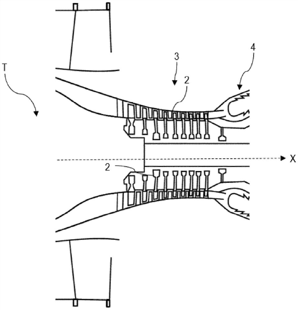
[0046] refer to figure 1 , which shows that the turbine T extends longitudinally along the axis X and is capable of driving the aircraft by causing the flow of air entering the turbine T to flow from upstream to downstream. In the following, the terms "upstream" and "downstream" are defined relative to an axis X oriented from upstream to downstream. Similarly, the terms "inner" and "outer" are defined with respect to the radial direction of the longitudinal axis X. As is known, the turbomachine T comprises a compressor 3 , a combustion chamber 4 and a turbine that drives the compressor 3 in rotation. The compressor 3 comprises one or more rotors 2 mounted about a longitudinal axis X to compress the gas flow flowing from upstream to downstream in the main duct of the turbine.

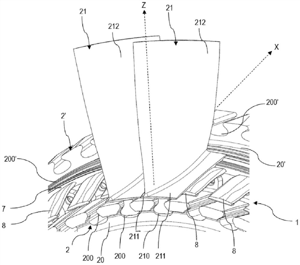
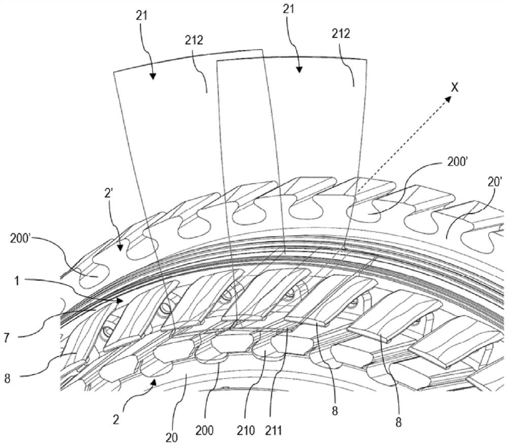
[0047] Such as figure 2 As shown, the rotor 2 includes a rotor disk 20 extending transversely with respect to the longitudinal axis X and a plurality of blades 21 , and the rotor disk 20 is integrall...


PUM


Abstract

The invention relates to an aircraft turbomachine rotor (2) comprising a rotor disc (20) extending transversely with respect to a longitudinal axis X, a plurality of blades (21) and a damping device (1) comprising: a support ring (7) configured to extend transversely with respect to the longitudinal axis X and configured to be mounted on the outer periphery of the rotor disc (20), and a plurality of damping members (8) that are integrally formed with the support ring (7) and extend projecting upstream from the support ring (7), each damping member (8) being configured to extend at least under a platform (211) of a blade (21) so as to exert a radially outward force so as to damp the radial movement of the blade (21) when the turbomachine is in operation.

Description

technical field [0001] The invention relates to the field of turbines for propelling aircraft. The invention relates more particularly to an aircraft turbine rotor comprising a rotor blade damping arrangement. Background technique [0002] It is known that an aircraft turbine extends longitudinally along an axis X and can drive the aircraft by causing the airflow entering the turbine to flow from upstream to downstream. In the following, the terms "upstream" and "downstream" are defined with respect to the longitudinal axis X oriented from upstream to downstream. Similarly, the terms "inner" and "outer" are defined with respect to the radial direction of the longitudinal axis X. As is known, a turbomachine comprises a compressor, a combustion chamber and a turbine that drives the compressor in rotation. The compressor comprises one or more rotors mounted about a longitudinal axis X to compress the gas flow flowing from upstream to downstream in the main duct of the turbin...

Claims


Application Information

Patent Timeline
IPC IPC(8): F01D5/22F01D5/26F01D5/30
CPCF01D5/22F01D5/26F01D5/3007F01D5/30F05D2240/80F05D2260/96Y02T50/60F01D11/006F01D5/10F05D2220/323F05D2240/24
Inventor 尼古拉斯·杰拉德·贝尼托·康奈克
Owner SAFRAN AIRCRAFT ENGINES SAS
Learn More