Sputum suction equipment for pediatric department
A pediatric and equipment technology, applied in the field of medical equipment, can solve problems such as inability to relieve discomfort, and achieve the effects of avoiding irreversible damage, avoiding stress reactions, and reducing discomfort
- Summary
- Abstract
- Description
- Claims
- Application Information
AI Technical Summary
Problems solved by technology
Method used
Image

Examples
Embodiment 1
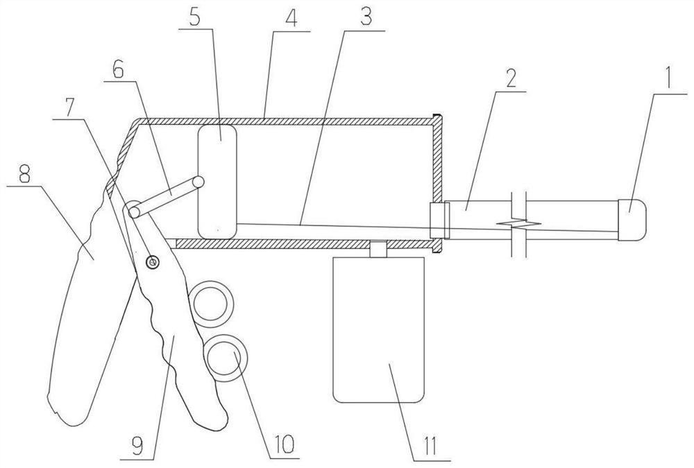
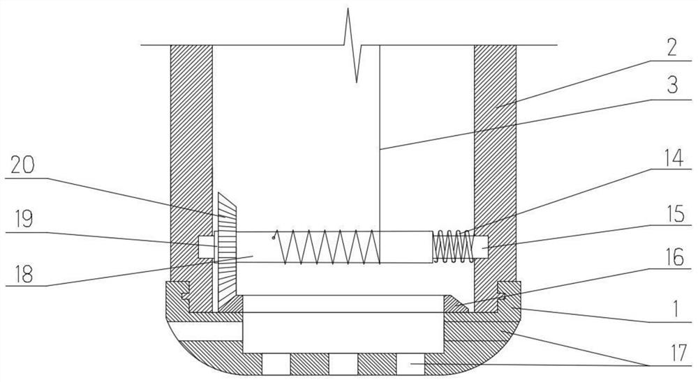
[0025] Such as figure 1 As shown, the main body of a pediatric sputum suction device in this embodiment is the same as the conventional sputum suction device, and still includes a sputum suction tube 2, a sputum suction head 1 arranged at the head end of the sputum suction tube 2, and a Negative pressure device. Such as figure 2 As shown, a plurality of suction holes 17 are evenly spaced on the front end and the circumference of the suction head 1. After the suction head 1 is placed in the patient's airway, negative pressure is generated by a negative pressure device to suck out the sputum in the airway.
[0026] The sputum suction device of this embodiment is gun type, and its negative pressure device constitutes the gun type main body, including the sputum suction tube 4 as the gun body, the handle 8 as the handle of the gun, and the swing rod 9 as the trigger. The sputum suction tube 4 is a circular straight tube with a circular linear cavity inside and closed at both en...
Embodiment 2
[0037] The main structure of this embodiment is the same as that of Embodiment 1, so no special drawings are provided for illustration. The effect of this embodiment is different from that of Embodiment 1: in this embodiment, the suction head 1 is only driven to rotate when the pull wire 3 pulls the rotating shaft 15 to rotate, and the suction head is not moved when the rotating shaft 15 is driven to rotate by the reset torsion spring 14 1 rotation, so as to achieve the corresponding rotation of the suction head 1 only during negative pressure suction, and the effect that the suction head 1 does not rotate in the non-negative pressure suction state, thereby further reducing the noise caused by the rotation of the suction head 1 Discomfort, to further reduce the discomfort of patients, especially infant patients, during sputum suctioning treatment.
[0038] In order to achieve the above-mentioned technical effect, the difference between the present embodiment and the embodiment...
Embodiment 3
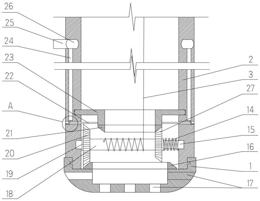
[0041] This embodiment includes all the technical solutions of Embodiment 2, and on the basis of Embodiment 2, this embodiment also includes an anesthetic agent spraying mechanism. The anesthetic agent spraying mechanism is triggered when the rotating shaft 15 is driven to rotate by the return torsion spring 14, as an interspersion between two sputum suction operations to further reduce the patient's discomfort during the sputum suction process.
[0042] to combine image 3 and Figure 4 As shown, the anesthetic agent spraying mechanism includes an elastic tube 30 arranged in the wall of the sputum suction tube 2 and a lever 22 for moving the elastic tube 30 . The inner side of the tube wall at the head end of the sputum suction tube 2 is provided with a relief groove 31 to avoid interference with the rotation track of the outer end of the driving lever 22. The relief groove 31 is annular and is continuously opened on the wall of the sputum suction pipe 2. A plurality of str...
PUM
 Abstract
Description
Claims
Application Information
 - R&D Engineer
- R&D Manager
- IP Professional
- Industry Leading Data Capabilities
- Powerful AI technology
- Patent DNA Extraction
Browse by: Latest US Patents, China's latest patents, Technical Efficacy Thesaurus, Application Domain, Technology Topic.
© 2024 PatSnap. All rights reserved.Legal|Privacy policy|Modern Slavery Act Transparency Statement|Sitemap