U-shaped steel bar lifting appliance

A steel bar, U-shaped technology, applied in the direction of load hanging components, transportation and packaging, etc., can solve the problems of low engineering quality, low lifting efficiency, poor safety, etc., to improve construction efficiency, simple and convenient operation and maintenance, prevent The effect of falling off and hurting

Active Publication Date: 2021-11-30
HUAZHONG UNIV OF SCI & TECH +2
View PDF4 Cites 0 Cited by
  • Summary
  • Abstract
  • Description
  • Claims
  • Application Information

AI Technical Summary

Problems solved by technology

[0005] Aiming at the above defects or improvement needs of the prior art, the present invention provides a U-shaped steel bar spreader, the purpose of which is to solve the problems of poor safety, low engineering quality and low lifting efficiency in the lifting process of U-shaped steel bars in the prior art. question

Method used


Image

  • U-shaped steel bar lifting appliance
  • U-shaped steel bar lifting appliance
  • U-shaped steel bar lifting appliance

Examples


Embodiment Construction

[0037] In order to make the object, technical solution and advantages of the present invention clearer, the present invention will be further described in detail below in conjunction with the accompanying drawings and embodiments. It should be understood that the specific embodiments described here are only used to explain the present invention, not to limit the present invention. In addition, the technical features involved in the various embodiments of the present invention described below can be combined with each other as long as they do not constitute a conflict with each other.

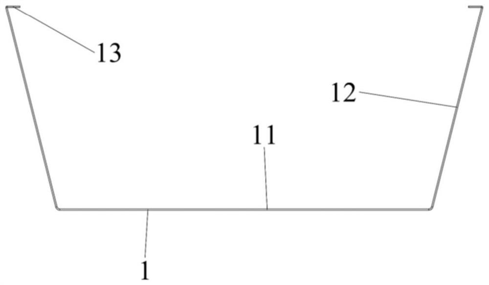
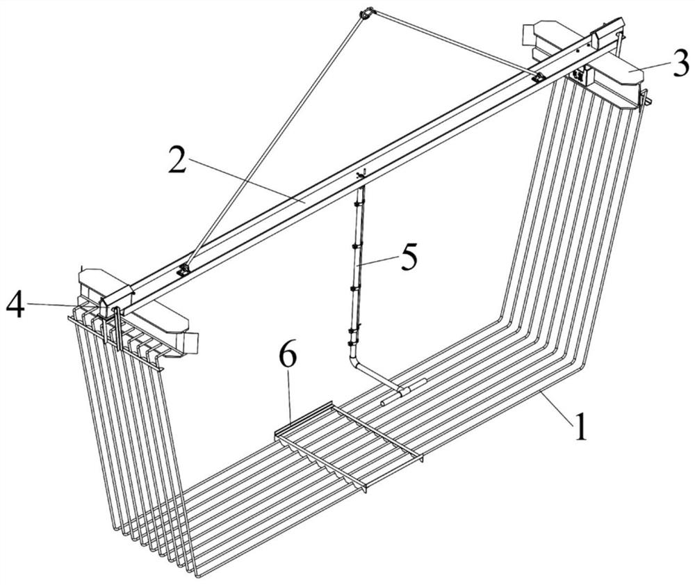
[0038] A kind of U-shaped steel bar spreader that the embodiment of the present invention provides, such as figure 2 As shown, it includes a channel steel main girder module 2, two H-shaped steel secondary girder modules 3, two electric drive slotted stop bar modules 4, a hand held steel pipe module 5 and a hand placed rectangular positioning frame module 6, wherein:

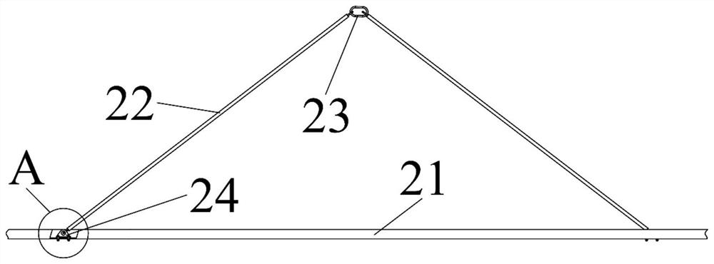
[0039] Such as image 3 A...


PUM


Abstract

The invention belongs to the field of load hanging mechanical devices, and particularly discloses a U-shaped steel bar lifting appliance. The U-shaped steel bar lifting appliance comprises a channel steel main beam, H-shaped steel secondary beams and electric drive grooved stop lever modules, wherein the two H-shaped steel secondary beams are installed at the two ends of the channel steel main beam correspondingly, top plates of the H-shaped steel secondary beams are fixed to the channel steel main beam, bottom plates of the H-shaped steel secondary beams are used for hooking U-shaped steel bars, the electric drive grooved stop lever modules are arranged corresponding to the H-shaped steel secondary beams and comprise driving assemblies, connecting rods and stop levers, and the driving assemblies are installed on the channel steel main beam and used for driving the connecting rods to rotate, the stop levers are fixed at the lower ends of the connecting rods, and a row of equidistant V-shaped notches are formed in the stop levers and used for buckling the U-shaped steel bars. The U-shaped steel bar lifting appliance is safe and reliable to operate, high in engineering quality and capable of remarkably improving the lifting efficiency.

Description

technical field [0001] The invention belongs to the field of load hanging mechanical devices, and more specifically relates to a U-shaped steel bar hanger. Background technique [0002] In the construction of high-speed railway bridges, U-shaped steel bars are a special shape ribbed steel bar that is used in large quantities in the production of reinforced concrete box girders, such as figure 1 Shown, its feature has the longest U-shaped steel bar bottom 11, the inclined U-shaped steel bar waist 12 and the shorter U-shaped steel bar ear 13 parallel with the bottom. When making the steel frame of the box girder, it is necessary to transport the U-shaped steel bar to the binding mold of the steel frame and realize its accurate positioning and laying in the mold. [0003] The current technical solution is: the first step is to manually tie several U-shaped steel bars stacked horizontally together at the waist with iron chains or wire ropes; The steel frame is tied into the mo...

Claims


Application Information

Patent Timeline
Patent Type & Authority Applications(China)
IPC IPC(8): B66C1/10
CPCB66C1/10
Inventor 熊蔡华孙晨露梁杰俊一唐爱华程坤华张上伟李建军
Owner HUAZHONG UNIV OF SCI & TECH
Why Eureka
Try Eureka