

A U-shaped steel bar hanger
A steel bar, U-shaped technology, applied in the direction of load hanging components, transportation and packaging, can solve the problems of low project quality, low lifting efficiency, poor safety, etc., to improve construction efficiency, simple and convenient operation and maintenance, prevent Falling off the hurting effect
Active Publication Date: 2022-05-31
HUAZHONG UNIV OF SCI & TECH +2
View PDF0 Cites 0 Cited by
- Summary
- Abstract
- Description
- Claims
- Application Information
AI Technical Summary
Problems solved by technology
[0005] Aiming at the above defects or improvement needs of the prior art, the present invention provides a U-shaped steel bar spreader, the purpose of which is to solve the problems of poor safety, low engineering quality and low lifting efficiency in the lifting process of U-shaped steel bars in the prior art. question
Method used
View moreImage
Smart ImageViewing Examples

Examples
Embodiment Construction
[0042] The lithium battery 47 is used as a power source in the drive assembly, and is fixed on the H-shaped steel secondary beam web 31 area near the center of the sling;
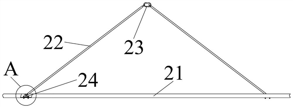
[0046] The retrofit pin 53 includes a retrofit pin shaft 534 and a plug guide ring 531, and the retrofit pin shaft 534 is attached to the main steel pipe 511
Login to View More PUM
 Abstract
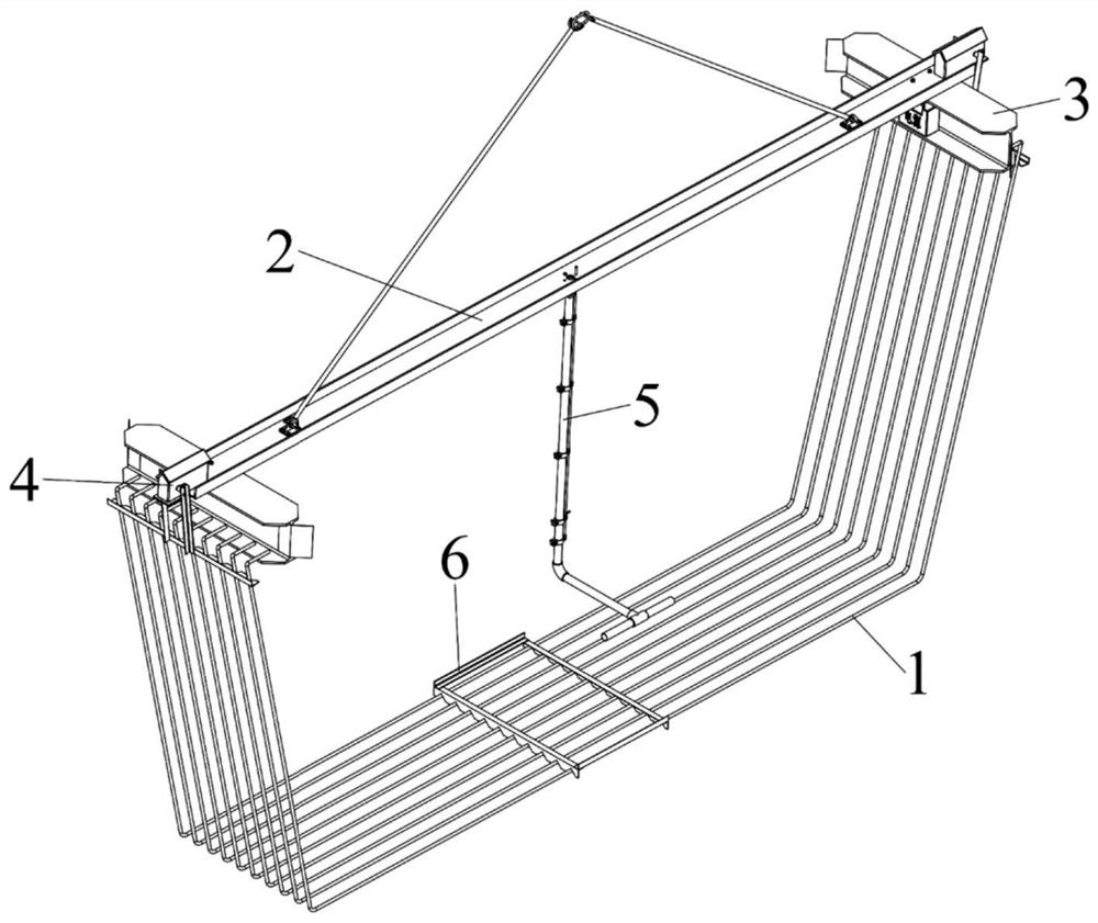
The invention belongs to the field of load hanging mechanical devices, and specifically discloses a U-shaped steel bar hanger, which includes a channel steel main beam, an H-shaped steel secondary beam, and an electric-driven slotted stop bar module, wherein: two H-shaped steel secondary beams respectively installed at both ends of the channel steel main beam, the top plate of the H-shaped steel secondary beam is fixed on the channel steel main beam, and the bottom plate is used to hook U-shaped steel bars; The beam is correspondingly arranged, which includes a driving assembly, a connecting rod and a blocking rod, the driving assembly is installed on the channel steel main beam, and is used to drive the connecting rod to rotate; the blocking rod is fixed at the lower end of the connecting rod, A row of equidistant V-shaped notches are provided on the retaining rod for snapping U-shaped steel bars. The U-shaped steel bar hanger of the invention is safe and reliable in operation, has high engineering quality, and can significantly improve hoisting efficiency.
Description
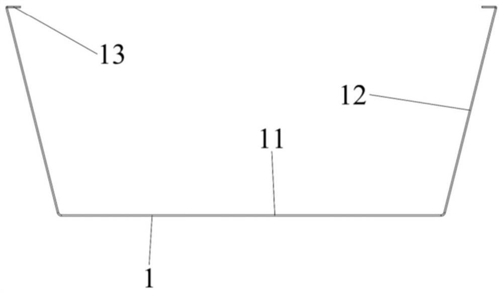
A U-shaped steel bar hanger technical field [0001] The invention belongs to the field of load-hanging mechanical devices, and more particularly, relates to a U-shaped steel bar spreader. Background technique In high-speed railway bridge construction, U-shaped steel bar is a kind of characteristic that the quantity used during the production of reinforced concrete box girder is more. The special shape ribbed steel bar, as shown in Figure 1, is characterized by the longest U-shaped steel bar bottom 11, the inclined U-shaped steel bar waist 12 and the The bottom is parallel to the shorter U-shaped steel bar ears 13. When making the steel frame of the box girder, it is necessary to transport the U-shaped steel bar to the steel frame to tie it. Puncture the tire and realize its accurate positioning and laying in the tire. Current technical scheme is: the first step, artificially several U-shaped steel bars stacked horizontally together use iron chain or The steel wire ...
Claims
Login to View More Application Information
Patent Timeline
 Patent Type & AuthorityPatents(China)
IPC IPC(8): B66C1/10
CPCB66C1/10
Inventor熊蔡华孙晨露梁杰俊一唐爱华程坤华张上伟李建军
OwnerHUAZHONG UNIV OF SCI & TECH