Method of forming a one-time-programming (OTP) bit

A Technology of Bits and Resistive Components

Active Publication Date: 2021-11-30
NS POLES TECH CORP
View PDF6 Cites 0 Cited by
  • Summary
  • Abstract
  • Description
  • Claims
  • Application Information

AI Technical Summary

Problems solved by technology

This third state is used for One Time Programmable (OTP), but the resistance distribution of this state is wider, making it prone to higher read error rate and circuit complexity

Method used

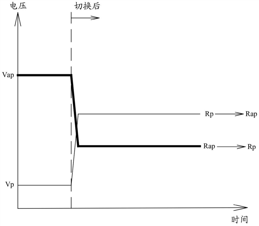
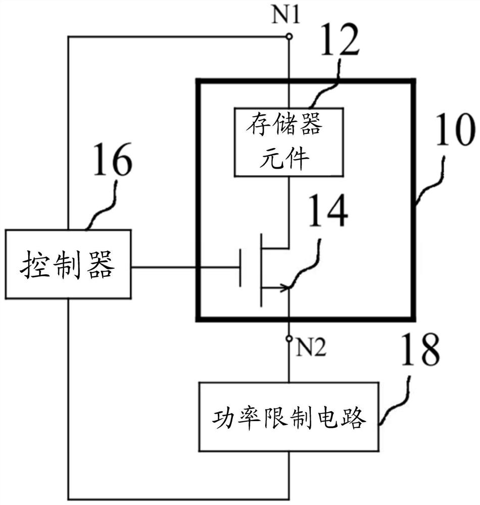
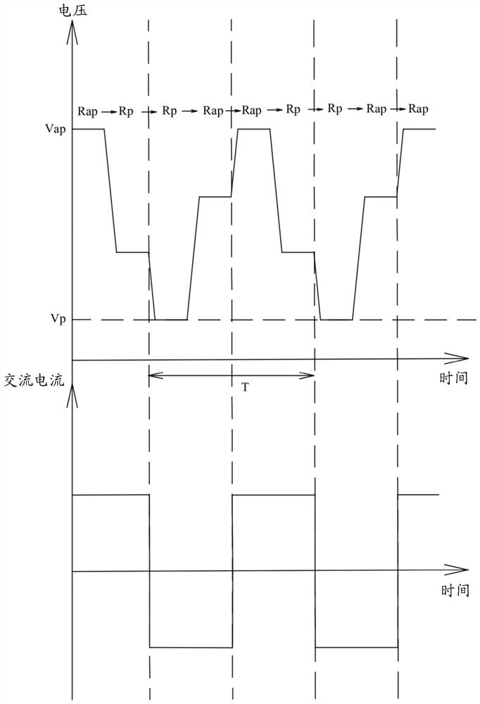

Image

  • Method of forming a one-time-programming (OTP) bit
  • Method of forming a one-time-programming (OTP) bit
  • Method of forming a one-time-programming (OTP) bit

Examples


Embodiment Construction

[0021] The following will clearly and completely describe the technical solutions in the embodiments of the present invention with reference to the accompanying drawings in the embodiments of the present invention. Obviously, the described embodiments are only some, not all, embodiments of the present invention. Based on the embodiments of the present invention, all other embodiments obtained by persons of ordinary skill in the art without making creative efforts belong to the protection scope of the present invention.

[0022] In order to make the above objects, features and advantages of the present invention more comprehensible, the present invention will be further described in detail below in conjunction with the accompanying drawings and specific embodiments.

[0023] When an element is referred to as being "on", it can generally mean that the element is directly on other elements, or there may be other elements present in between. Conversely, when an element is referred...


PUM


Abstract

Disclosed is a method of forming a one-time-programming (OTP) bit. In the method of forming a one-time-programming (OTP) bit, a thin-film memory device is provided, which includes at least one memory element and a transistor, and the memory element is coupled to the transistor in series. Then, an alternating current is applied to the memory element and the transistor, the power applied to the memory element is constrained, and the transistor is turned on to change the resistance of the memory element for a plurality of cycles of the alternating current until the resistance of the memory element is irreversibly changed.

Description

technical field [0001] The present invention relates to the field of memory, relates to a method for forming a bit, and in particular to a method for forming a single programmable bit. Background technique [0002] Thin film memory devices, such as Magnetic Random Access Memory (MRAM), typically include a tunneling barrier that can represent two resistive states. The permanent third state produced by barrier collapse has lower resistance compared to the two resistive states preceding barrier collapse. This third state is used for One Time Programmable (OTP), but the resistance distribution of this state is wider, making it prone to higher read error rate and circuit complexity. In addition, for power consumption considerations, it is desirable to operate with a lower barrier breakdown voltage and to choose a smaller transistor size. Contents of the invention [0003] The present invention aims at the above problems, and proposes a method for forming one-time programmable...

Claims


Application Information

Patent Timeline
Patent Type & Authority Applications(China)
IPC IPC(8): G11C17/16G11C11/15G11C13/00H01L43/08H01L27/22
CPCG11C17/165G11C11/15G11C13/0002G11C13/0004G11C13/0011H10B61/00H10N59/00H10N50/10G11C17/18G11C17/02G11C11/16G11C11/22G11C2213/79G11C17/146G11C11/1675G11C16/225
Inventor 柯昱州
Owner NS POLES TECH CORP
Why Eureka
Try Eureka