Filler circuit unit

A technology of circuit units and circuits, applied in the direction of electrical components, logic circuits, pulse technology, etc., can solve problems such as damaged transistors

Active Publication Date: 2010-08-18
UNITED MICROELECTRONICS CORP
View PDF0 Cites 0 Cited by
  • Summary
  • Abstract
  • Description
  • Claims
  • Application Information

AI Technical Summary

Problems solved by technology

[0005] Although the above known filling circuit unit can be used to fill up the gaps between the units, since the gate 16 of the NMOS transistor 12 and the gate 20 of the PMOS transistor 14 in the filling circuit unit are directly connected to the voltage source Vss or Vdd, when When a pulse waveform interference (glitch) occurs, the sudden bias will cause the concentrated current to be directly directed into the gate dielectric layer / inversion layer on the surface of the transistor channel and damage the entire transistor

Method used


Image

  • Filler circuit unit
  • Filler circuit unit
  • Filler circuit unit

Examples


Embodiment Construction

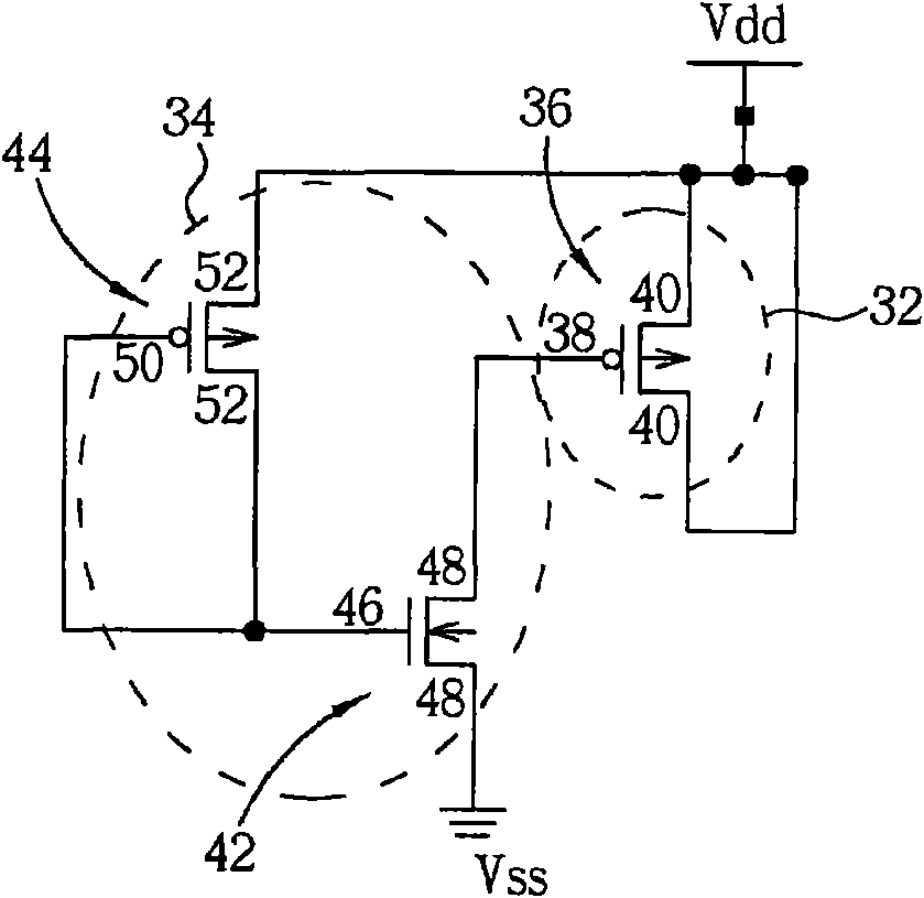
[0039] Please refer to figure 2 , figure 2 It is a schematic circuit diagram of a filling circuit unit in a preferred embodiment of the present invention. As shown in the figure, the filling circuit unit of the present invention mainly includes a decoupling capacitor 32 and a voltage stabilizing unit 34 connected to the decoupling capacitor 32 . Wherein, the decoupling capacitor 32 includes a transistor, such as a PMOS transistor 36 . The PMOS transistor 36 includes a gate 38 , a source 40 and a drain 40 . The voltage stabilizing unit 34 includes an NMOS transistor 42 and a PMOS transistor 44 . The NMOS transistor 42 includes a gate 46 , a source 48 and a drain 48 , and the PMOS transistor 44 includes a gate 50 , a source 52 and a drain 52 .

[0040] In this embodiment, a source / drain 52 of the PMOS transistor 44 in the voltage stabilizing unit 34 is directly connected to a voltage source Vdd, and the gate 50 and the other source / drain 52 are connected to the NMOS transi...


PUM


Abstract

The invention discloses a filler circuit unit, which comprises a decoupling capacitor, a tie low circuit and a tie high circuit, wherein the decoupling capacitor comprises a first N-type metal-oxide semiconductor (NMOS) transistor and a first P-type metal-oxide semiconductor (PMOS) transistor; the source/drain of the first NMOS transistor is connected with a second power supply; the source/drain of the first PMOS transistor is connected with a first power supply; the tie low circuit comprises a second NMOS transistor and a second PMOS transistor; and the tie high circuit comprises a third NMOS transistor and a fourth PMOS transistor.

Description

technical field [0001] The invention relates to a filling circuit unit, in particular to a filling circuit unit matched with low-connection and high-connection circuits. Background technique [0002] In today's digital integrated circuit design process, in order to meet the requirements of high automation, a standard cell library is usually used to complete the required layout design. Since the standard cell library already has various commonly used cell types (cell types), such as basic logic gate circuits such as AND, OR, NOT, etc., customers can apply the existing cell types in the standard cell library according to the designed architecture to quickly spell out desired design. [0003] In order to meet the requirements of the manufacturing process, each design unit usually presents a rectangular shape when pieced together by automated tools, so that the input / output terminals (I / O) can be smoothly arranged around the completed design unit. In most cases, a complete des...

Claims


Application Information

Patent Timeline
Patent Type & Authority Applications(China)
IPC IPC(8): H03K19/0944
Inventor 许振贤王建国
Owner UNITED MICROELECTRONICS CORP
Why Eureka
Try Eureka