Supercharge Your Innovation With Domain-Expert AI Agents!

Zero-current switch control circuit

A switch control circuit and zero current technology, applied in the direction of control/regulation system, electrical components, adjustment of electrical variables, etc., can solve the problems of consumption, limiting the conversion efficiency of DC-DC converters, and large equivalent impedance of diodes, etc., to achieve reduction Effects of power consumption, reduction of equivalent impedance, and small on-resistance

Active Publication Date: 2021-11-30
NINGBO UNIV
View PDF2 Cites 0 Cited by
  • Summary
  • Abstract
  • Description
  • Claims
  • Application Information

AI Technical Summary

Problems solved by technology

The traditional DC-DC converter mainly includes modules such as switches, inductors, diodes, and corresponding switch control circuits. First, a circuit for charging the inductor is formed by controlling the switch. When the inductor current rises to a certain value, the switch is reconfigured again. Form a loop in which the inductor discharges to the load; in the traditional converter, in the inductor discharge stage, in order to prevent the load from pouring energy into the inductor after the inductor energy is released, a diode is generally connected in series between the inductor and the load to prevent the load energy from leaking. However, the equivalent impedance of the diode is relatively large, which will consume part of the energy during the discharge phase of the inductor, which seriously limits the conversion efficiency of the DC-DC converter.

Method used


Image

  • Zero-current switch control circuit

Examples


Embodiment Construction

[0007] The present invention will be further described in detail below in conjunction with the accompanying drawings and embodiments.

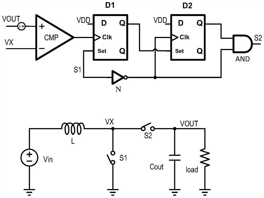
[0008] A zero-current controllable switch control circuit, comprising a DC power supply Vin, an inductor L, a first controllable switch S1 that is turned on when the control terminal is at a high level, a second controllable switch S2 that is turned on when the control terminal is at a high level, Energy storage capacitor Cout, comparator CMP, first D flip-flop D1, second D flip-flop D2, inverter N, two-input AND gate AND and load resistor load, the positive end of the DC power supply Vin is connected to one end of the inductor L , the negative terminal of the DC power supply Vin is grounded, the other terminal of the inductor L, one terminal of the first controllable switch S1, one terminal of the second controllable switch S2 and the negative input terminal of the comparator CMP are connected, and the other terminal of the first controllable ...


PUM


Abstract

The invention discloses a zero-current controllable switch control circuit which is characterized by comprising a direct-current power supply, an inductor, a first controllable switch, a second controllable switch, an energy storage capacitor, a comparator, a first D trigger, a second D trigger, a phase inverter, a two-input AND gate and a load resistor, wherein the first controllable switch is switched on when a control end is at a high level, and the second controllable switch is switched on when the control end is at the high level. The circuit has the advantages that the controllable switch is used for replacing a fly-wheel diode in a traditional converter, the equivalent impedance of an inductor discharge loop is effectively reduced, the conversion efficiency of the converter is improved, the zero-current switch control technology detects the voltage of the positive discharge end and the output end of the inductor, the controllable switch is switched off when the discharge current of the inductor is reduced to zero, and energy backflow at the output end is prevented. Compared with a traditional freewheeling diode, the conduction impedance of the controllable switch is much smaller, the power consumption of the whole circuit is reduced, and the energy conversion efficiency is improved.

Description

technical field [0001] The invention relates to a controllable switch DC step-up circuit structure, in particular to a zero-current switch control circuit. Background technique [0002] At present, DC-DC converters are widely used in various fields such as photovoltaic energy harvesting, electric vehicles, household appliances, mobile electronic devices, and Internet of Things nodes. The traditional DC-DC converter mainly includes modules such as switches, inductors, diodes, and corresponding switch control circuits. First, a circuit for charging the inductor is formed by controlling the switch. When the inductor current rises to a certain value, the switch is reconfigured again. Form a circuit in which the inductor discharges to the load; in the traditional converter, in the inductor discharge stage, in order to prevent the load from pouring energy into the inductor after the inductor energy is released, a diode is generally connected in series between the inductor and the ...

Claims


Application Information

Patent Timeline
IPC IPC(8): H02M1/088H02M3/158
CPCH02M1/088H02M3/158Y02B70/10
Inventor 夏银水王修登芦泓宇
Owner NINGBO UNIV
Features
  • R&D
  • Intellectual Property
  • Life Sciences
  • Materials
  • Tech Scout
  • Unparalleled Data Quality
  • Higher Quality Content
  • 60% Fewer Hallucinations
Learn More