Foot sole wearable device and motion control method

A wearable device and sole technology, which is applied in electrotherapy, medical science, pressure sensors, etc., can solve the problems of limited freedom of movement, large equipment volume, and complex structure, and achieve matching, small equipment volume, and low energy consumption. low effect

Pending Publication Date: 2021-12-03
BEIJING AI ROBOTICS TECH CO LTD +1
View PDF0 Cites 0 Cited by
  • Summary
  • Abstract
  • Description
  • Claims
  • Application Information

AI Technical Summary

Problems solved by technology

[0004] The purpose of the present invention is to solve the problems of complex structure, large equipment volume, limited freedom of movement and high energy consumption in traditional wearable equipment

Method used


Image

  • Foot sole wearable device and motion control method
  • Foot sole wearable device and motion control method
  • Foot sole wearable device and motion control method

Examples


Embodiment Construction

[0026] Herein, the detailed content and technical description of the present invention will be further described with a preferred embodiment, but it should not be construed as a limitation to the implementation of the present invention.

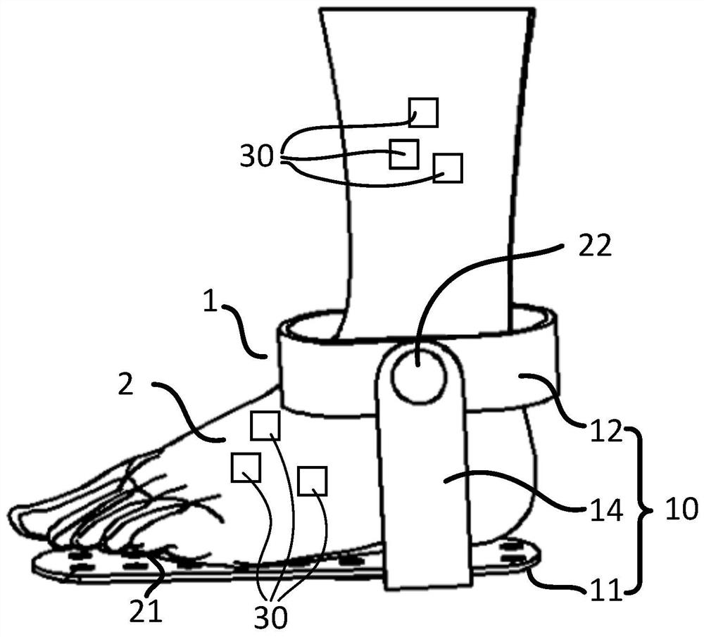
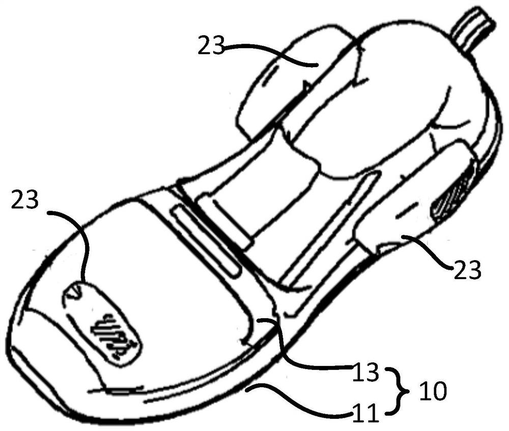
[0027] figure 1 and figure 2 A schematic diagram of a foot wearing device 1 according to an embodiment herein is shown. like figure 1 As shown, the device 1 basically includes a body 10 , at least one sensor 21 , 22 , 23 , a plurality of electrode pads 30 , and a sensor (not shown) in communication with the at least one sensor 21 , 22 , 23 and the plurality of electrode pads 30 .

[0028] The main body 10 is worn on the user's foot 2 . like figure 1 and figure 2 As shown, the main body 10 may include a sole plate 11 located under the foot 2 , and after the user wears the device 1 , his foot 2 steps on the sole plate 11 . The main body 10 may further include a ring member 12 disposed around the ankle joint of the foot 2 and connected t...


PUM


Abstract

The invention provides a foot sole wearable device. The foot sole wearable device comprises a foot sole plate worn below the foot sole of a user, a plurality of electrode plates, one or more sensors, and a controller, wherein the electrode plates are used for collecting gait information when a user walks, and are attached to the feet and the shanks of the user; and the controller is in communication with the sensors and the electrode plates, the used for controlling and outputting a current for stimulating the muscle to the electrode plates according to gait information collected from the one or more sensors. The invention further provides a motion control method using the foot sole wearable device.

Description

technical field [0001] This paper involves human motion control, more specifically, this paper designs a foot wearable device and motion control method based on electrical stimulation. Background technique [0002] At present, most of the existing devices that realize the control of human motion posture are wearable devices. After the user wears this kind of motion control device, the wearable device realizes the motion control of the mechanical structure through motor drive or hydraulic drive, and then assists or Drive the user to perform motion posture control. That is, the existing wearable device applies an external force to the user through an external driving device, so that the user passively controls the movement posture under the action of the external force. [0003] However, the structure of the wearable device in the prior art is complex, the device is bulky, and the freedom of movement of the mechanism is difficult to achieve a complete match with the joints of...

Claims


Application Information

Patent Timeline
Patent Type & Authority Applications(China)
IPC IPC(8): A61B5/103A61B5/11A61B5/00A61N1/36
CPCA61B5/1038A61B5/112A61B5/1116A61B5/1121A61B5/6807A61N1/36003A61N1/36014A61N1/36031A61B2562/0247
Inventor 帅梅陈亚平
Owner BEIJING AI ROBOTICS TECH CO LTD
Why Eureka
Try Eureka