
Correction bracket for spine surgery

A surgical and spine technology, applied in medical science, massage auxiliary products, electronic timers, etc., can solve the problems of low comfort, single corrective training method, and inability to accurately implement corrective training plan time planning, etc., to improve comfort , the effect of promoting recovery

Inactive Publication Date: 2021-12-03
詹春霞
View PDF1 Cites 0 Cited by
  • Summary
  • Abstract
  • Description
  • Claims
  • Application Information

AI Technical Summary

Problems solved by technology

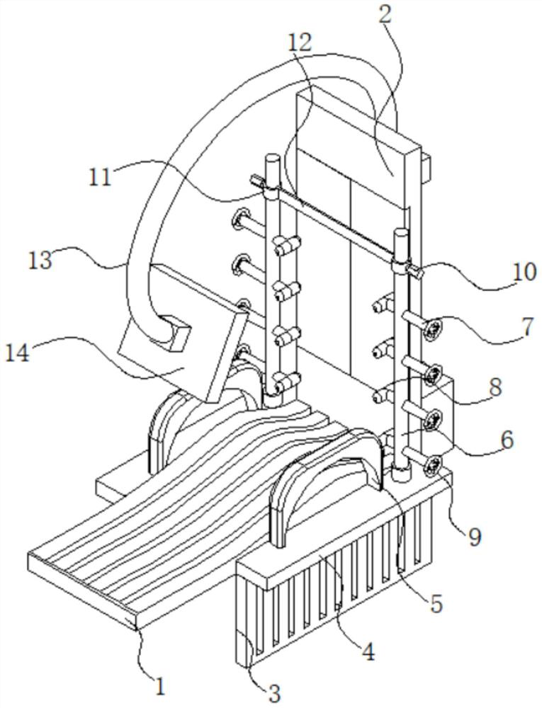
[0008] The purpose of the present invention is to provide a correction bracket for spinal surgery, through the arrangement of threaded columns, positioning columns, control panels, electric push rods and massage cushion structures, it solves the ineffectiveness of the existing correction brackets for spine surgery in positioning the patient's spine. Good, the patient's comfort level is low in the correction training, the correction training method is single, and the time planning of the correction training plan cannot be accurately implemented

Method used


Image

  • Correction bracket for spine surgery
  • Correction bracket for spine surgery
  • Correction bracket for spine surgery

Examples


Embodiment Construction

[0034] The following will clearly and completely describe the technical solutions in the embodiments of the present invention with reference to the drawings in the embodiments of the present invention.

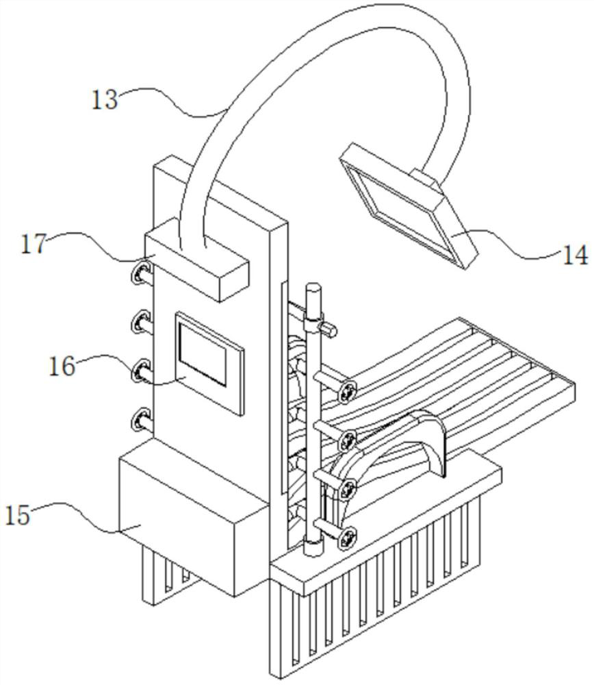
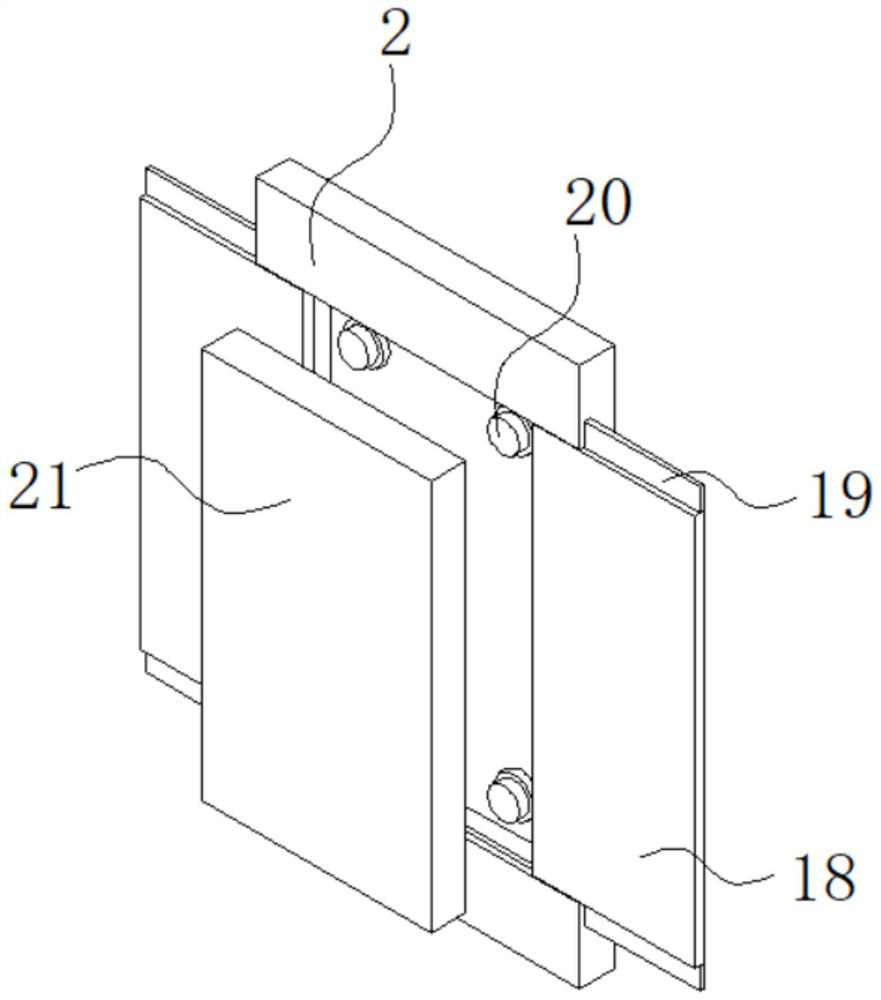
[0035] see Figure 1-7As shown, the present invention is a correction bracket for spinal surgery, including a base 1, the tail of the base 1 is fixedly connected with a backrest 2, and the rear parts of both sides of the base 1 are fixedly connected with a horizontal plate 4, and the upper and rear ends of the horizontal plate 4 are fixed A vertical rod 6 is connected, and the lower part of the vertical rod 6 is equidistantly and evenly threaded with a threaded column 7, the inner end of the threaded column 7 is fixedly connected with a positioning column 8, and the outer end of the threaded column 7 is fixedly connected with a handle 9, and the center of the inner side of the backrest 2 The sliding door 18 is slidingly connected inside the position, and the backrest 2 is prov...


PUM


Abstract

The invention discloses a correction bracket for spine surgery, and relates to the technical field of medical equipment. The correction bracket for the spine surgery comprises a base, a backrest is fixedly connected to the tail of the base, transverse plates are fixedly connected to the rear portions of the two sides of the base, vertical rods are fixedly connected to the rear ends of the upper sides of the transverse plates, threaded columns are evenly connected to the lower portions of the vertical rods at equal intervals in a threaded mode, positioning columns are fixedly connected to the inner ends of the threaded columns, a sliding door is slidably connected in the center of the inner side of the backrest, a massage cushion is arranged in the backrest, the output end of an electric push rod is fixedly connected to the corner of the back face of the massage cushion, a massage assembly arranged in a mounting frame of the massage cushion is electrically connected with a motor, and a control panel and a power box are fixedly connected to the lower portion of the back face of the backrest. By arranging the threaded columns to control advancing and retreating of the positioning columns, controlling the correction training time through the control panel and arranging the massage cushion capable of being stored, the spine of the patient can be conveniently positioned, the training comfort and the training effect of the patient are improved, and the training plan time of the patient is accurately controlled.

Description

technical field [0001] The invention belongs to the technical field of medical equipment, in particular to a correction bracket for spinal surgery. Background technique [0002] Medical equipment refers to instruments, equipment, utensils, materials or other items that are used alone or in combination on the human body, including the required software. Spinal correction refers to a device that is specially used to reset the deviated or subluxed spine and adjust the vertebral joints. The door technology is similar to the pulling method and bone setting in Chinese medicine. With the development of medical technology, there are more and more devices for spinal correction, such as: [0003] Existing public documents, authorization announcement number CN209564269U a spinal surgery correction device, related to the technical field of spinal correction devices, including a back pad, one side of the back pad is provided with a patch pocket, the outer surface of the back pad is locat...

Claims


Application Information

Patent Timeline
Patent Type & Authority Applications(China)
IPC IPC(8): A61F5/01A61H7/00G04G13/02
CPCA61F5/0104A61H7/007G04G13/02A61H2201/1207A61H2205/081
Inventor 詹春霞
Owner 詹春霞
Learn More