High-efficiency low-temperature denitration device for high-dust flue gas
A low-temperature denitration and flue gas technology, applied in the field of flue gas denitration, can solve the problems of difficult adjustment of the contact time between flue gas and solvent, poor contact effect of flue gas and solvent, and poor denitration effect of flue gas, etc. Response effect, effect of improving cleanliness
- Summary
- Abstract
- Description
- Claims
- Application Information
AI Technical Summary
Problems solved by technology
Method used
Image

Examples
Embodiment 1
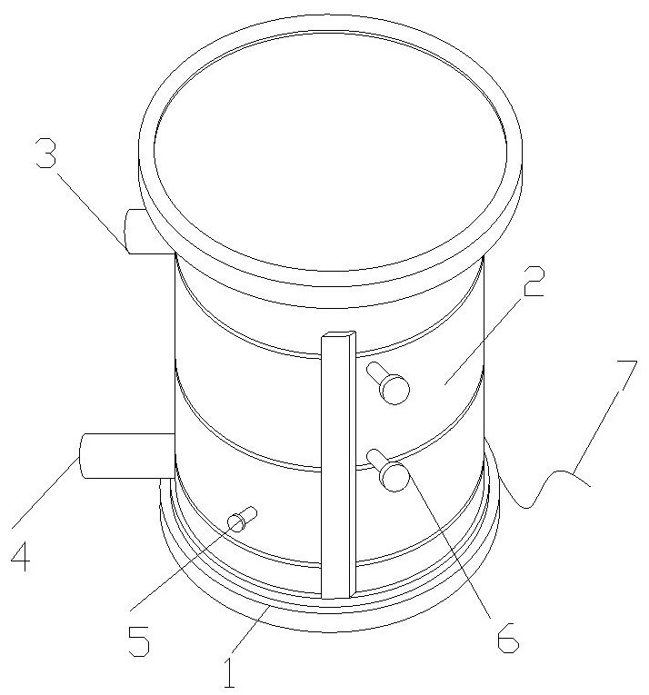
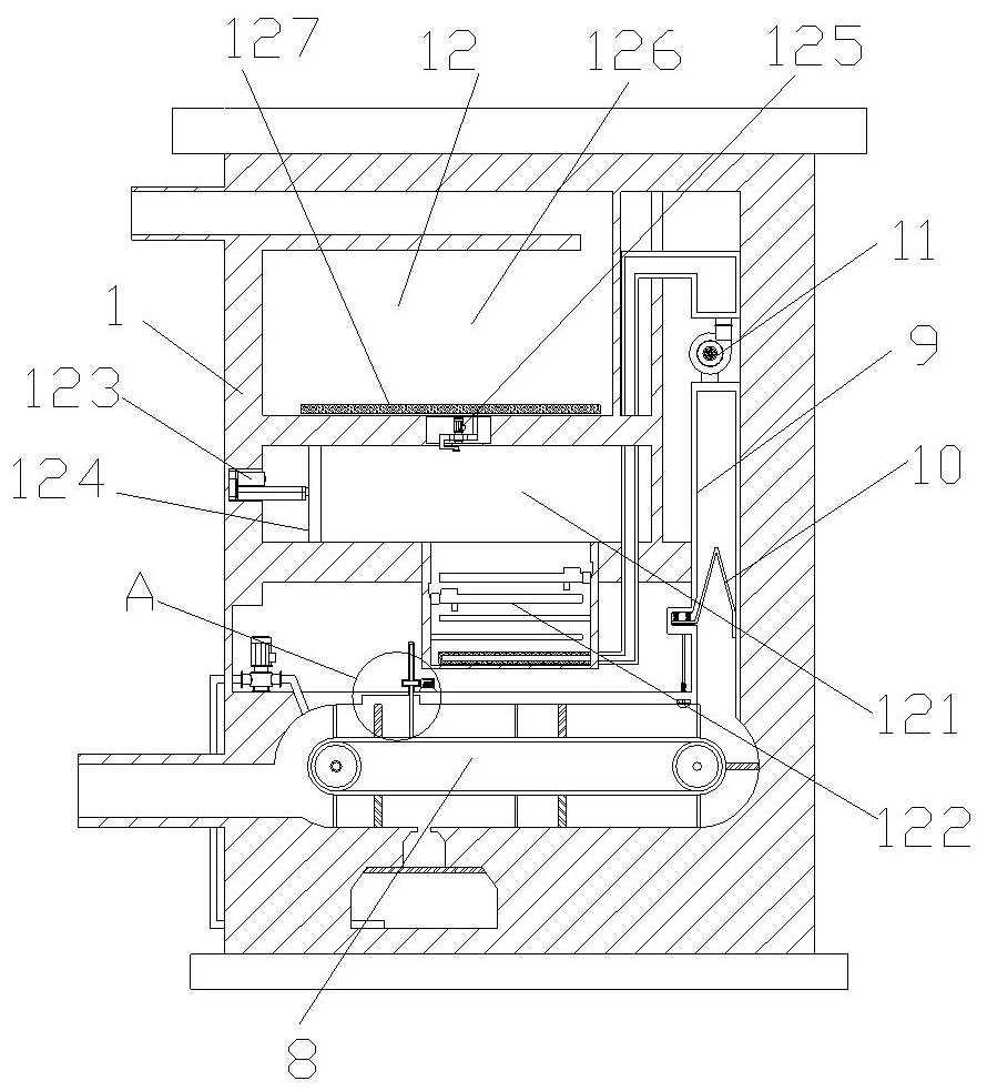
[0034] see figure 1 with figure 2 , a high-efficiency low-temperature denitrification device for high-dust flue gas of the present invention includes a bottom frame 1, a main body 2, a smoke outlet 3, a smoke inlet 4, a drain pipe 5, a water outlet pipe 6, a power cord 7, and a transmission assembly 8 , the smoke collecting groove 9, the dust filter 10, the exhaust fan 11 and the receiving assembly 12, the top of the bottom frame 1 is fixedly connected with the main body 2, and the upper and lower ends of the left side of the main body 2 are connected with the smoke outlet 3 and the smoke inlet 4 respectively, The main body 2 is provided with drain pipes 5 and water outlet pipes 6 on the upper and lower sides of the front surface, the back end of the main body 2 is provided with a power cord 7, and the right end of the main body 2 is provided with a smoke collecting groove 9, and the lower end of the smoke collecting groove 9 is connected to the smoke inlet 4. Through, the m...
Embodiment 2
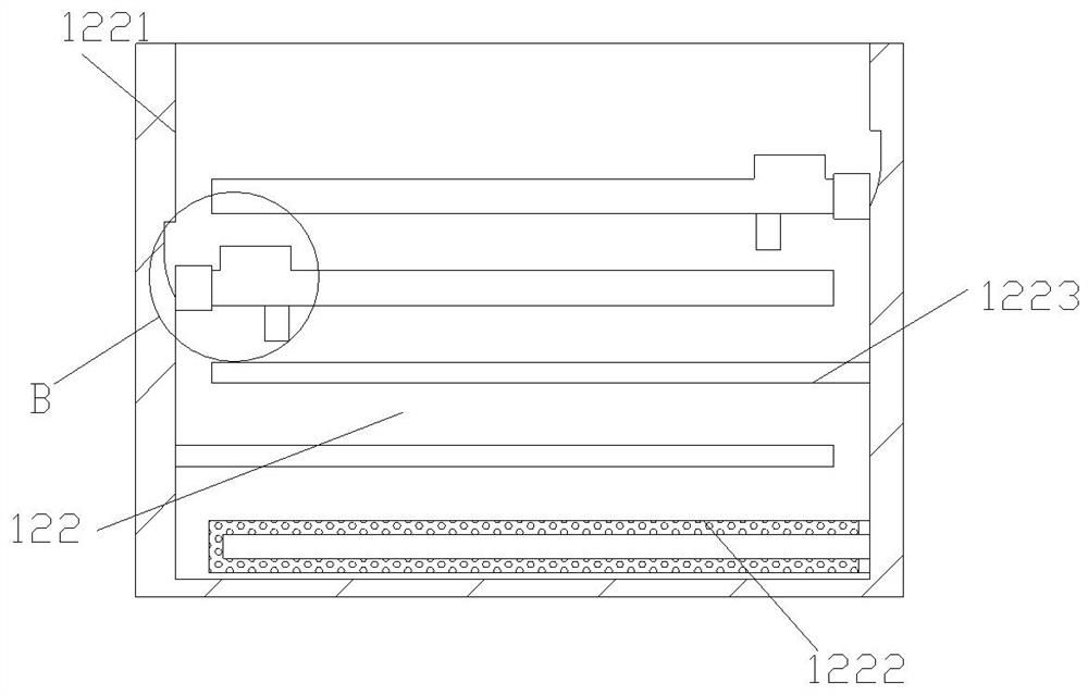
[0041] A high-efficiency low-temperature denitrification device for high-dust flue gas of the present invention, the base of the power motor 1228 is connected with the inner top of the partition 1223 to improve the stability of the connection, and the left end of the blocking plate 12210 is connected to the limiting plate 1226 to facilitate blocking The connection between the plate 12210 and the second gear screw 1229, the second gear screw 1229 can drive the blocking plate 12210 to move, the water inlet pipe at the left end of the water pump 811 extends outward to the side of the main body 2, and the water inlet pipe at the left end of the water pump 811 is U-shaped. The shaped structure is convenient for the recycling of the cleaning liquid during cleaning.
[0042] The present invention provides a high-efficiency low-temperature denitrification device for high-dust flue gas through improvement, and its working principle is as follows;
[0043] First, when using this device,...
PUM
| Property | Measurement | Unit |
|---|---|---|
| Length | aaaaa | aaaaa |
Abstract
Description
Claims
Application Information