
Pipeline cleaning device and method

A pipeline cleaning and pipeline technology, applied in cleaning methods and utensils, chemical instruments and methods, cleaning hollow objects, etc., can solve problems such as low efficiency and insignificant cleaning effect, and achieve good cleaning effect and pipeline cleaning cycle. The effect of shortening and reducing energy consumption

Inactive Publication Date: 2021-12-03
CHENGXI SHIPYARD
View PDF7 Cites 1 Cited by
  • Summary
  • Abstract
  • Description
  • Claims
  • Application Information

AI Technical Summary

Problems solved by technology

[0004] The purpose of the present invention is to provide a pipeline cleaning device and its method to solve the problems of low efficiency and inconspicuous cleaning effect in the traditional pipeline cleaning method

Method used


Image

  • Pipeline cleaning device and method
  • Pipeline cleaning device and method
  • Pipeline cleaning device and method

Examples


Embodiment 1

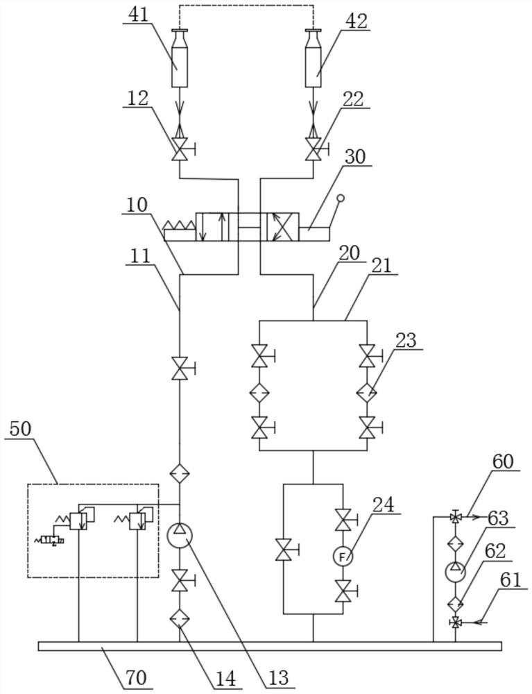
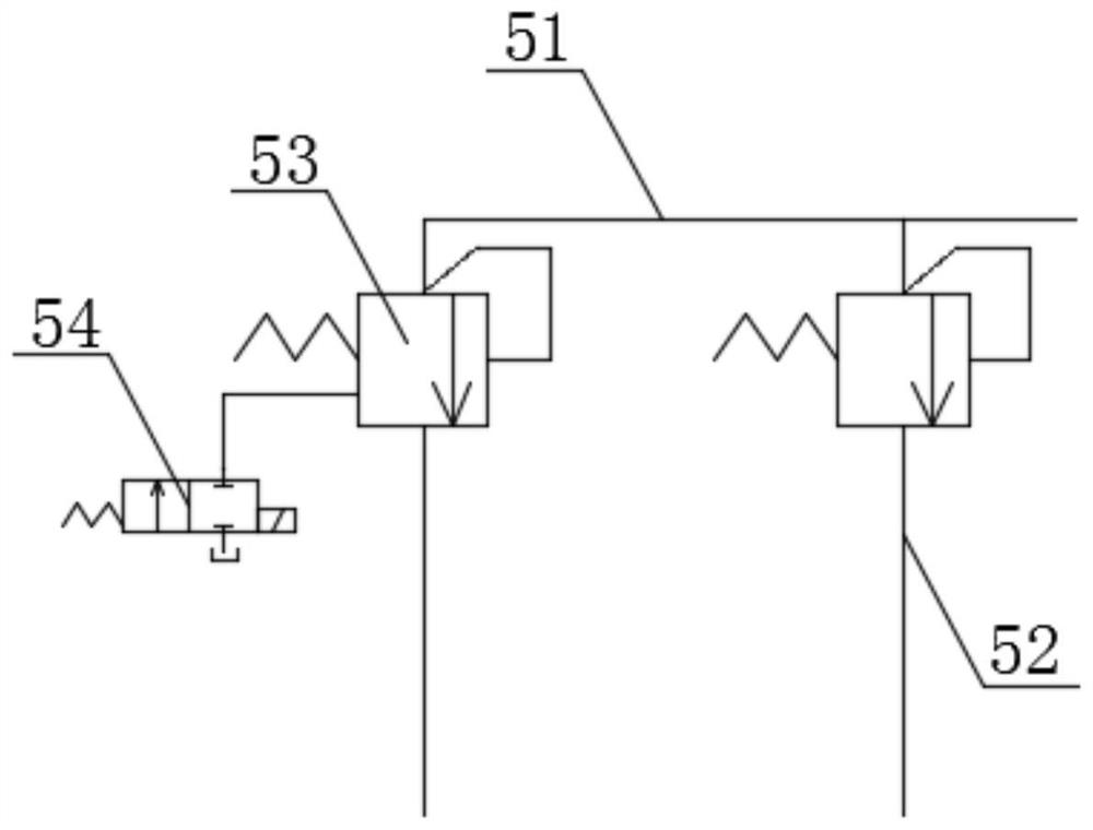
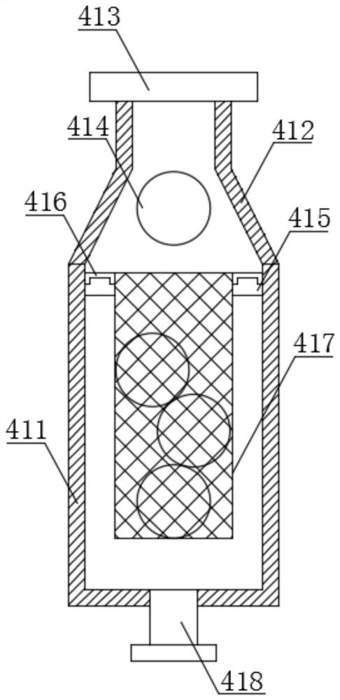
[0042] see Figure 1-3 The present invention provides a technical solution: a pipeline cleaning device, including a first pipeline cleaning component 10 , a second pipeline cleaning component 20 , a reversing device 30 , a pulse component 50 , a refueling component and a liquid flow channel 70 .

[0043] In this embodiment, specifically, the reversing device 30 specifically adopts a three-position four-way manual reversing valve.

[0044] Wherein, the first pipeline cleaning assembly 10 includes a first cleaning pipeline 11 , and a first high-pressure ball valve 12 , a cleaning screw pump 13 , a switching valve and a first fine filter 14 are arranged outside the first cleaning pipeline 11 .

[0045] In this embodiment, specifically, there are two first fine filters 14 on the first cleaning pipeline 11, one of the on-off valves is set between the liquid inlet pipe 43 and the liquid outlet pipe 44, and the other on-off valve is set Between the cleaning screw pump 13 and the fir...

Embodiment 2

[0070] see Figure 4 , the present invention provides a technical solution: a pipeline cleaning method, comprising the following steps:

[0071] S1. First, connect the two ends of the ship pipeline to be cleaned to the first cleaning connection seat and the second cleaning connection seat respectively, so that the ship pipeline is connected end to end to form a pipeline;

[0072] S2. Then stop the handle of the reversing device in the middle position, and the cleaning oil forms an internal circulation in the equipment, which can complete the starting of the screw pump and the heating of the oil;

[0073] S3, and then rotate the handle of the reversing device 45° clockwise, the cleaning oil enters the outer circulation of the cleaning pipeline from the first cleaning pipeline, and then enters the second cleaning connection seat from the second cleaning pipeline, and then Enter the pipeline of the ship to be cleaned, and the cleaning ball and cleaning oil will clean the pipelin...


PUM


Abstract

The invention discloses a pipeline cleaning device and method. The pipeline cleaning device comprises a first pipeline cleaning component and a second pipeline cleaning component, wherein the first pipeline cleaning component comprises a first cleaning pipeline; a first high-pressure ball valve, a cleaning screw pump, a switch valve and a first fine filter are arranged outside the first cleaning pipeline; the second pipeline cleaning component comprises a second cleaning pipeline; and a second high-pressure ball valve, a second fine filter, a switch valve and a pressure gauge are arranged outside the second cleaning pipeline. According to the pipeline cleaning device, through arranged cleaning balls, cleaning oil drives the cleaning balls in a net cover to flow into a second cleaning connecting seat along a ship pipeline along with the cleaning oil; and in the process, the cleaning balls rub against the inner wall of the ship pipeline, the cleaning oil is combined to achieve the dual cleaning effect on the ship pipeline, forward and reverse cleaning of the pipeline can be achieved, and therefore, the inner wall cleaning effect of the ship pipeline is better.

Description

technical field [0001] The invention relates to the technical field of ship pipeline cleaning, in particular to a pipeline cleaning device and a method thereof. Background technique [0002] In the process of ship repairing and building, it involves the production and installation of oil medium pipes. In order to ensure that the system hydraulic pumps, valves and other equipment operate in a clean environment, oil circulation for pipeline cleaning is an important link in pipeline construction. Ensure that the mechanical impurities or other particles left in the pipe during the production, pickling, and installation processes can be removed to achieve the cleanliness required for the normal operation of the system. [0003] However, at present, a power unit composed of a hydraulic pump is usually used to absorb the hydraulic oil in the oil tank in the unit and drive the cleaning medium in the cleaning pipeline to flow. Since certain impurities will adhere to the inner wall of...

Claims


Application Information

Patent Timeline
Patent Type & Authority Applications(China)
IPC IPC(8): B08B9/057
CPCB08B9/057
Inventor 汤传春
Owner CHENGXI SHIPYARD
Learn More