
Centralized control device for electric operating mechanism of electrified railway isolating switch

A technology of electric operating mechanism and electrified railway, applied in the direction of power device, circuit device, air switch parts and so on inside the switch, can solve the problem of disconnecting switch malfunction, contactor, relay malfunction, railway catenary power supply and distribution System security hidden dangers and other issues, to achieve the effect of reliable cutting

Active Publication Date: 2016-05-11
CHINA RAILWAY DESIGN GRP CO LTD +1
View PDF5 Cites 0 Cited by
  • Summary
  • Abstract
  • Description
  • Claims
  • Application Information

AI Technical Summary

Problems solved by technology

The remote control command adopts the optical fiber transmission method. Due to the limitation of optical fiber transmission in low temperature environment, cable transmission is used in low temperature environment. Considering the serious interference of long-distance cable laying, it is easy to cause contactors and relays to be closed by mistake, which will lead to isolation. Faults such as misoperation and refusal of the switch have caused potential safety hazards in the power supply and distribution system of the railway catenary

Method used


Image

  • Centralized control device for electric operating mechanism of electrified railway isolating switch

Examples


Embodiment Construction

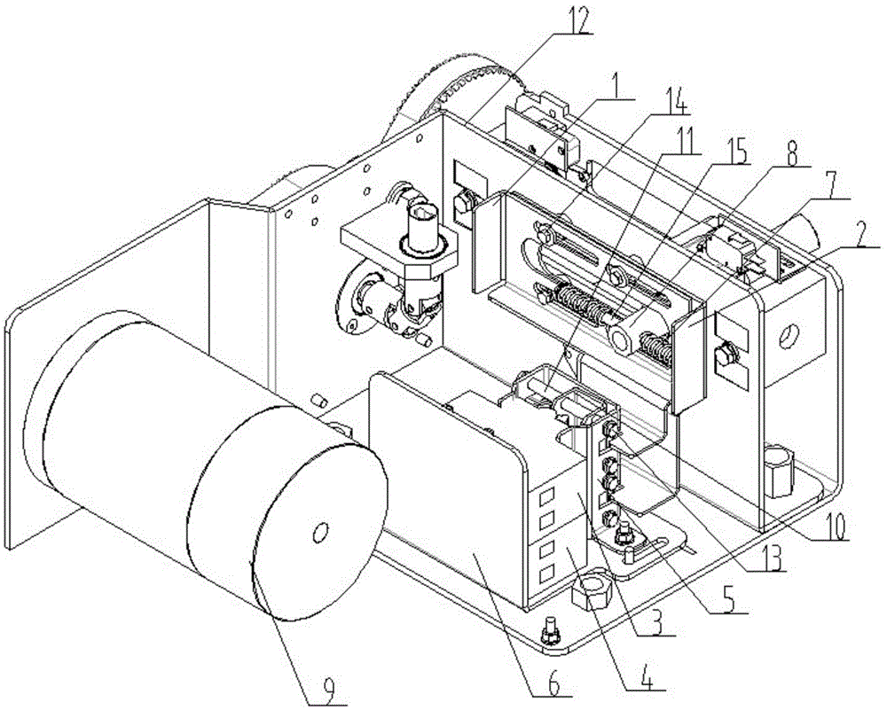
[0013] The structure of the centralized control device for the electric operating mechanism of the electric railway isolation switch of the present invention will be described with reference to the accompanying drawings.

[0014] The electric operating mechanism of the electrified railway isolating switch of the present invention adopts the screw and nut drive mode combined with the circuit breaker, and uses the mechanical transmission mode to replace the general contactor and relay control mode. The circuit breaker can reliably cut off the DC motor power supply and effectively Avoid the risk of malfunction or refusal of the electric operating mechanism due to the attenuation and interference of the remote control signal.

[0015] A centralized control device for an electric operating mechanism of an electric railway isolating switch of the present invention includes a circuit breaker switch plate A1, a circuit breaker switch plate B2, an opening circuit breaker 3, a closing circuit...


PUM


Abstract

The invention provides a centralized control device for an electric operating mechanism of a disconnecting switch of an electrified railway, wherein the device is characterized in that a circuit breaker shifting plate A and a circuit breaker shifting plate B of the device are both fixed on a main driving lower plate through interval studs, and move back and forth along the interval stud channels of the interval studs under the driving of a nut; a circuit breaker installation plate is fixed on a main driving bottom plate; a switch-off circuit breaker and a switch-on circuit breaker are arranged at one side of the circuit breaker installation plate; a circuit breaker clamping groove is arranged in the other side of the circuit breaker installation plate; the circuit breaker clamping groove, the switch-off circuit breaker and the switch-on circuit breaker are clamped on the circuit breaker installation plate through fastening bolts; the nut is arranged in the channel of the main driving lower plate; each of two ends of a guiding rod is provided with a spring which is locked by a bolt; the guiding rod freely moves through a reserved hole position of the nut. The centralized control device for the electric operating mechanism of the disconnecting switch of the electrified railway has the beneficial effects that electric and electronic component devices are eliminated, mechanical driving components are employed, and the positive and reverse rotations of a motor are directly controlled by a power supply, so that a system fault rate is effectively reduced, and the high-voltage line movement stability is beneficially guaranteed.

Description

Technical field [0001] The invention relates to a centralized control device for an electric operating mechanism of an electrified railway isolating switch, which is installed in the electric operating mechanism of a high-voltage isolating switch. The forward and reverse switching of a DC motor can be realized through two sets of circuit breakers, and the power supply is automatically cut off after the operating mechanism is in place. Features. Background technique [0002] At present, the electric operating mechanism of the isolation switch, as an actuator for operating the isolation switch, its safety and reliability have attracted much attention. Under normal circumstances, the electric operating mechanism uses contactors and relays to control the forward and reverse switching of the motor. The remote control opening and closing commands trigger the self-holding circuit of the electric operating mechanism, and the motor automatically completes the remaining actions. The remot...

Claims


Application Information

Patent Timeline
Patent Type & Authority Patents(China)
IPC IPC(8): H01H31/02H01H3/26
CPCH01H3/26H01H31/02H02J13/0003
Inventor 陈兴强孙震洋张涛邵明陈杰孟凡兴刘金和翟成亮冯学良
Owner CHINA RAILWAY DESIGN GRP CO LTD
Learn More