
Automatic clamping strip mounting device and mounting method thereof

An automatic installation and clip technology, applied in metal processing, metal processing equipment, manufacturing tools, etc., can solve the problem that clips cannot meet production and processing needs, and achieve the effect of ensuring smooth installation, high position accuracy, and avoiding splits

Pending Publication Date: 2021-12-03
天津泓德汽车玻璃有限公司
View PDF0 Cites 0 Cited by
  • Summary
  • Abstract
  • Description
  • Claims
  • Application Information

AI Technical Summary

Problems solved by technology

[0003] The purpose of the present invention is to provide an automatic installation device for clips, which is used in conjunction with a manipulator, to replace manual installation to improve production and processing efficiency in view of the technical defect that manual installation of clips cannot meet the needs of production and processing in the prior art.

Method used


Image

  • Automatic clamping strip mounting device and mounting method thereof
  • Automatic clamping strip mounting device and mounting method thereof
  • Automatic clamping strip mounting device and mounting method thereof

Examples


Embodiment 1

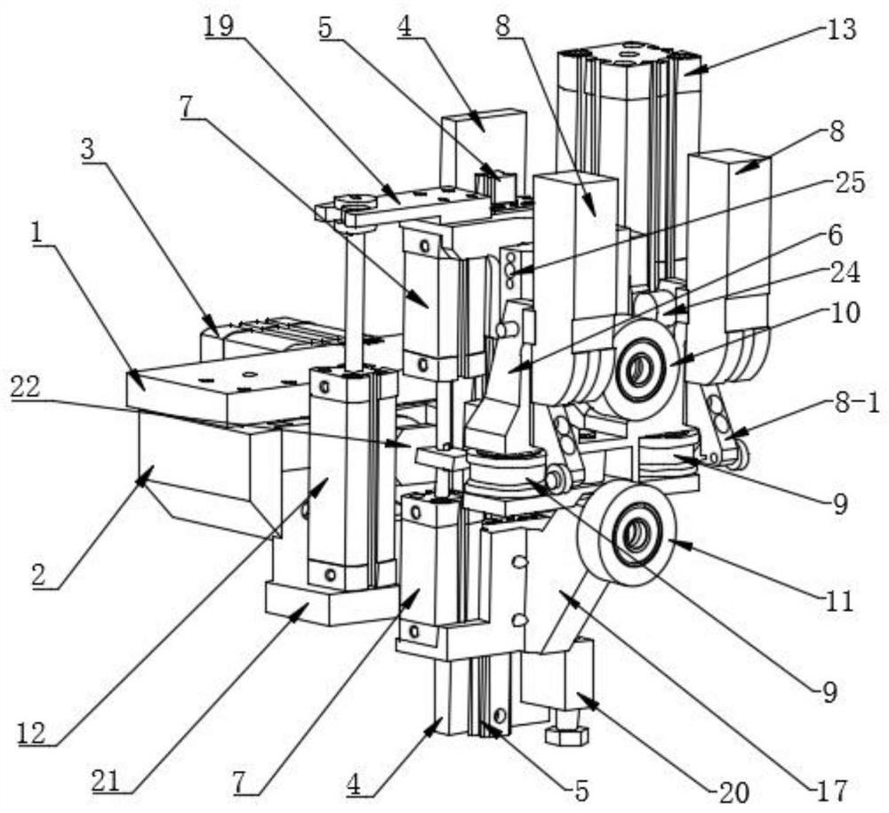
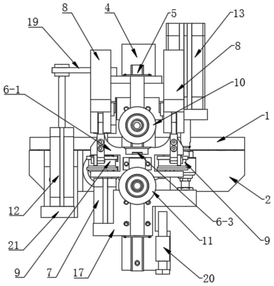
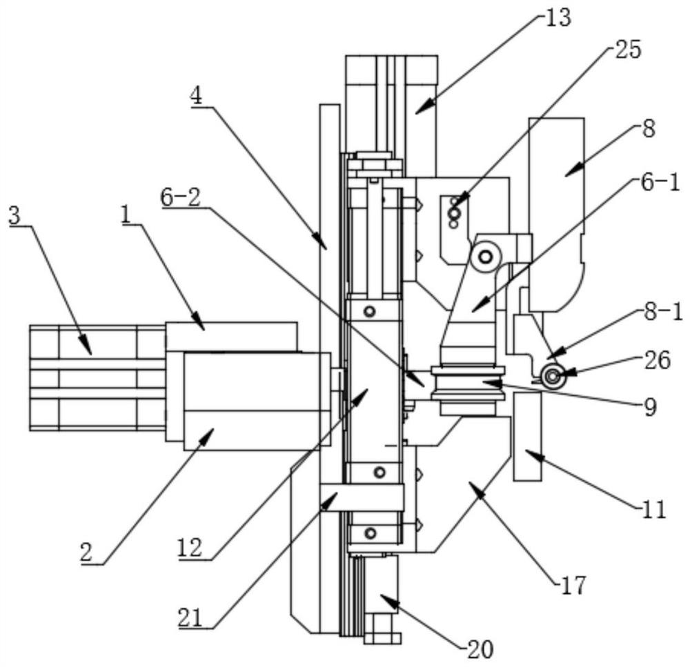
[0038] A kind of card strip automatic installation device, such as Figure 1-4 As shown, it includes an integral propulsion structure fixedly installed with the manipulator, a grasping structure for grabbing the strip to be clamped, and a rolling installation structure for installing the clamped strip on the glass;

[0039] Such as Figure 5 As shown, the overall propulsion structure includes a fixed installation plate 1 fixedly installed with the manipulator, a mobile frame 2 slidingly installed under the fixed installation plate 1, and a push cylinder 3, and the push cylinder 3 is installed on the fixed installation plate 1, its push rod pushes the mobile frame 2 to slide along the fixed installation plate 1, and the vertical connecting plate 4 is fixedly installed on the integral propulsion structure, and the connecting plate 4 is fixed with a Z direction slide rail 5;

[0040] The push cylinder and moving frame provide a flexible compensation device for the whole device,...

Embodiment 2

[0051] This embodiment introduces its installation method on the basis of Embodiment 1.

[0052] The installation method of the above-mentioned card strip automatic installation device mainly includes the following steps:

[0053] The manipulator drives the clip automatic installation device to reach the clip station, the pneumatic clamp 8 starts, and the profiling fixture 8-1 cooperates with the auxiliary roller 9 to grab the clip;

[0054] The manipulator drives the automatic strip installation device to the glass station, the upper pressing roller 10 is located above the glass, and the lower pressing roller 11 is located below the glass;

[0055] The pneumatic clamp 8 is closed, the profiling fixture 8-1 is lifted up, and the clamped strip is placed on the glass, and at the same time, the first clamping cylinder 12 and the second clamping cylinder 13 are activated, so that The upper pressing roller 10 presses the clamping strip downwards, the lower pressing roller 11 clamp...


PUM


Abstract

The invention discloses an automatic clamping strip mounting device. The automatic clamping strip mounting device comprises an integral pushing structure fixedly mounted with a manipulator, a grabbing structure used for grabbing a to-be-clamped strip and a rolling mounting structure used for mounting the clamping strip on glass. In the grabbing structure, a clamping strip is clamped through cooperation of a pneumatic clamp and an auxiliary roller. The rolling mounting structure is provided two pressing rollers which are arranged up and down and two clamping air cylinders which are respectively used for driving the two pressing rollers. The automatic clamping strip mounting device is moved to a clamping strip station through the manipulator, after the clamping strip is grabbed by the grabbing structure, the clamping strip is moved to a glass station through the manipulator, and then the clamping strip is mounted on glass in a rolling mode through the rolling mounting structure. The whole process is controlled by a control program, the position accuracy is high, the bonding area is determined, the installation deviation caused by human uncertain factors is greatly reduced, and meanwhile the production and machining efficiency is improved.

Description

technical field [0001] The invention relates to the technical field of automobile glass processing, in particular to an automatic installation device for clip strips and an installation method thereof. Background technique [0002] In the process of automobile glass processing, it is a very important production process to install ELK clips on the front windshield of the automobile. The current installation method is manual installation, and the clips are bonded to the proper position of the glass. There are many disadvantages in manual installation, such as the uncertainty of installation position and bonding area, low installation efficiency and increased labor costs. Contents of the invention [0003] The purpose of the present invention is to provide an automatic installation device for clips that can not meet the production and processing requirements in the prior art, which can be used in conjunction with manipulators to replace manual installation to improve product...

Claims


Application Information

Patent Timeline
Patent Type & Authority Applications(China)
IPC IPC(8): B23P19/02
CPCB23P19/02
Inventor 程大明李海涛任广新宋鹏贾海鹏魏炳川
Owner 天津泓德汽车玻璃有限公司
Learn More