Dry-method winding prepreg filament preparation equipment and preparation process thereof
A preparation process and dry winding technology, which is applied in the direction of building components, coatings, building insulation materials, etc., can solve the problems of solvent waste, pollution, and the inability to adjust the infiltration content of prepreg silk resin glue liquid, etc., to improve uniformity Effect
- Summary
- Abstract
- Description
- Claims
- Application Information
AI Technical Summary
Problems solved by technology
Method used
Image
Examples
Embodiment 1
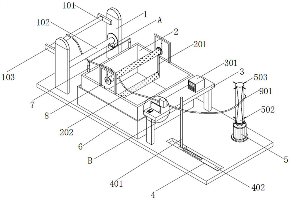
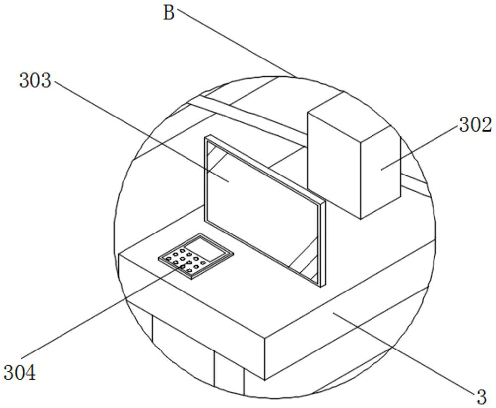
[0052] see figure 1 and image 3 , an embodiment provided by the present invention: a dry-process winding prepreg preparation equipment, including a vertical board 1, creel rods 102 are installed on the surfaces of the vertical boards 1 close to each other, and the bottom of the vertical board 1 is installed There is a base plate, and a water bath cylinder 6 is installed on the top of the base plate;
[0053] Specifically, the contact area between the manufacturing equipment and the installation surface can be increased through the bottom plate, thereby increasing the installation stability of the manufacturing equipment, and an electric heating tube is arranged inside the water bath cylinder 6, which can clean the inside of the dipping tank 2 placed therein. Carrying out heating treatment in a water bath, thereby ensuring uniform heating treatment of the resin glue liquid inside the dipping tank 2;
[0054] The top of the base plate is equipped with a support, and the suppo...
Embodiment 2
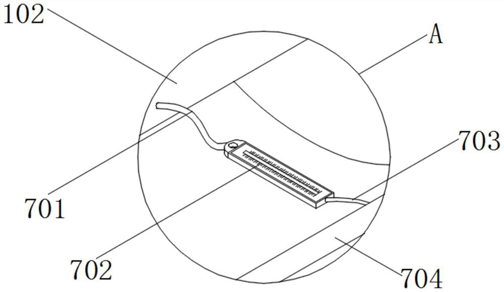
[0058] see figure 2 , an embodiment provided by the present invention: a dry-process winding prepreg preparation equipment, including a lift adjustment rod 7, the top side frame of the dipping tank 2 is equipped with a lift adjustment rod 7 arranged front and rear, the Crosspieces 704 are installed on the surfaces of the lifting adjustment rods 7 that are close to each other, and No. 2 stay rope 703 is installed on the rear surface of the crosspiece 704. An electronic tension gauge 702 is installed on one end of the No. 2 stay rope 703. One end of the electronic tension gauge 702 is installed with a No. 1 stay rope 701 , and the tail end of the No. 1 stay rope 701 is connected with the surface of the creel bar 102 .
[0059] Specifically, when tension needs to be applied to the fiber after yarn threading, the height of the lifting adjustment rod 7 can be adjusted, and then the crosspiece 704 is driven to rise synchronously. The tension effect is formed between the No. 2 stay...
Embodiment 3
[0061] see Figure 4 , Figure 5 and Figure 8 , an embodiment provided by the present invention: a dry-process winding prepreg preparation equipment, including a lifting adjustment rod 7, a winding motor 5 is installed on the top of the bottom plate, and the winding motor 5 is located on one side of the detection platform 3 On the side, the output end of the winding motor 5 is equipped with a round rod, the surface of the round rod is sleeved with a disc 501, and the surface of the round rod is fitted with a winding rod 502, and the winding rod 502 The diameter is smaller than the diameter of the disc 501 , and the top and bottom of the winding rod 502 are surrounded by limiting rods 503 , wherein the surfaces of two groups of the limiting rods 503 are sleeved with rubber loops 9 .
[0062] The surface of the rubber rope ring 9 is connected with a marking rope 901 , the surface of the marking rope 901 is surrounded by an adhesive layer 902 , and the outer surface of the adh...
PUM
| Property | Measurement | Unit |
|---|---|---|
| thickness | aaaaa | aaaaa |
Abstract
Description
Claims
Application Information
 - R&D
- Intellectual Property
- Life Sciences
- Materials
- Tech Scout
- Unparalleled Data Quality
- Higher Quality Content
- 60% Fewer Hallucinations
Browse by: Latest US Patents, China's latest patents, Technical Efficacy Thesaurus, Application Domain, Technology Topic, Popular Technical Reports.
© 2025 PatSnap. All rights reserved.Legal|Privacy policy|Modern Slavery Act Transparency Statement|Sitemap|About US| Contact US: help@patsnap.com


