An automatic forming device for polyurethane-lined pipes

An automatic forming, polyurethane technology, applied in the direction of tubular items, household appliances, other household appliances, etc., can solve the problems of difficulty in continuing to move, the steel rope is not tightened, and the anti-eccentric bracket is loosened, so as to achieve the effect of increasing the speed.

Active Publication Date: 2022-02-22
张家港力勤机械有限公司
View PDF3 Cites 0 Cited by
  • Summary
  • Abstract
  • Description
  • Claims
  • Application Information

AI Technical Summary

Problems solved by technology

[0004] In order to overcome the problem that when the anti-eccentric support is arranged by two people, the anti-eccentric support will be stuck and it will be difficult to continue to move if the two people cooperate improperly, and the anti-eccentric support needs to be tightened with a steel rope. , making the anti-eccentric bracket loose, the invention provides an automatic forming device for polyurethane-lined pipes

Method used


Image

  • An automatic forming device for polyurethane-lined pipes
  • An automatic forming device for polyurethane-lined pipes
  • An automatic forming device for polyurethane-lined pipes

Examples


Embodiment 1

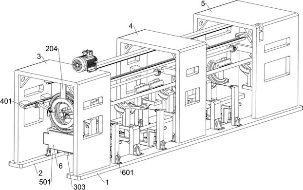
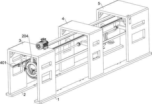
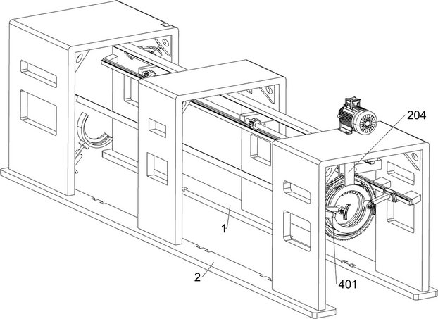
[0036] An automatic forming device for polyurethane-lined pipes, such as Figure 1-3 and Figure 9 As shown, it includes a first support plate 1, a second support plate 2, a first protective cover 3, a second protective cover 4, a third protective cover 5, a baffle plate 6, an equal division unit, a lifting unit and a carrying unit; A first protective cover 3 is welded to the front part of the upper surface of the first support plate 1 and the upper surface front of the second support plate 2; the second protective cover 4 is welded to the middle part of the upper surface of the first support plate 1 and the middle part of the upper surface of the second support plate 2 The rear part of the upper surface of the first support plate 1 and the rear part of the upper surface of the second support plate 2 are welded with a third protective cover 5; the lower part between the inner left wall and the inner right wall of the first protective cover 3 is welded with a baffle plate 6; A...

Embodiment 2

[0039] On the basis of Example 1, such as Figure 4-13 As shown, the equal division unit includes a first electric slider 201, a first electric slide rail 202, a first horizontal plate 203, a fixed plate 204, a circular guide rail 205, a gear ring 206, a dial assembly 207, an auxiliary plate 208, Push plate 209, fixed ring 2010, first fixed block 2011, driver 2012, first transmission wheel 2013, second transmission wheel 2014, first spur gear 2015, transmission shaft 2016, second spur gear 2017, third spur gear 2018 , the third bracket 2019, the second bracket 2020 and the first bracket 2021; the middle part of the lower surface of the first protective cover 3 is welded with the first transverse plate 203; the middle part of the lower surface of the second protective cover 4 and the middle part of the lower surface of the third protective cover 5 are both Welded with the first horizontal plate 203; the lower surface of the first horizontal plate 203 is bolted to the first elec...

Embodiment 3

[0047] On the basis of Example 2, such as figure 1 with Figure 15-16 As shown, a pulling unit is also included, the inner wall of the first protective cover 3 is connected with the pulling unit; the inner wall of the second protective cover 4 is connected with the pulling unit; the inner wall of the third protective cover 5 is connected with the pulling unit; the pulling unit Including a second electric slide rail 401, a second electric slider 402, a second connecting rod 403 and a third electric clamper 404; each bolt on the upper part of the inner left wall and the upper part of the inner right wall of the first protective cover 3 is connected with a first Two electric slide rails 401; The left wall top and the inner right wall top in the second protective cover 4 are respectively connected with a second electric slide rail 401 bolts; The two electric slide rails 401 are connected by bolts; each of the two second electric slide rails 401 is slidably connected with a second...


PUM


Abstract

The invention relates to the field of polyurethane-lined pipelines, in particular to an automatic molding device for polyurethane-lined pipelines. The technical problem is: when the anti-eccentric support is arranged by two people, improper operation will cause the anti-eccentric support to get stuck and it is difficult to continue to move, and the anti-eccentric support needs to be tightened with a steel rope. After repeated operations, the worker's arm is sore and the steel rope will be twisted. Not tight, making the anti-eccentric bracket loose. The technical solution is: an automatic forming device for polyurethane-lined pipelines, including a first support plate, a second support plate, a first protective cover, etc.; Connected with the first protective cover. The invention realizes the arrangement of the anti-eccentric support on the outer surface of the inner tube of the polyurethane pipeline, and at the same time ensures the equidistant distribution of the wooden blocks on the anti-eccentric support, replaces manual operation, and improves the dispersion rate of the wooden blocks; After sealing, leave a small hole to facilitate the perfusion of polyurethane between the inner tube and the rubber sleeve.

Description

technical field [0001] The invention relates to the field of polyurethane-lined pipelines, in particular to an automatic molding device for polyurethane-lined pipelines. Background technique [0002] The current polyurethane-lined pipe forming technology requires an anti-eccentric bracket to be arranged on the surface of the inner tube to prevent the offset of the rubber sleeve when the inner tube is covered with a rubber sleeve, and two people are required to cooperate when arranging the anti-eccentric bracket. At that time, the anti-eccentricity bracket would be stuck and it would be difficult to continue to move, prolonging the overall working time, and the anti-eccentricity bracket needs to be tightened with a steel rope. The bracket is loose, affecting the subsequent rubber sleeve, and even the quality of the polyurethane pipe has problems in the end. [0003] In summary, it is necessary to develop an automatic forming device for polyurethane-lined pipes to overcome th...

Claims


Application Information

Patent Timeline
Patent Type & Authority Patents(China)
IPC IPC(8): B29D23/00
CPCB29D23/001
Inventor 王汉力郭晓斌蒋波
Owner 张家港力勤机械有限公司
Why Eureka
Try Eureka