Two-speed transmission for new energy vehicles

A technology for new energy vehicles and transmissions, applied in vehicle gearboxes, motor vehicles, vehicle components, etc., can solve the problems of adjusting the reduction ratio, insufficient endurance, and reduced mileage, avoiding vibration or noise, and solving climbing jitters. Effect

Active Publication Date: 2022-07-12
杭州骑遇科技有限公司
View PDF5 Cites 0 Cited by
  • Summary
  • Abstract
  • Description
  • Claims
  • Application Information

AI Technical Summary

Problems solved by technology

The main reducer of the transmission system of the mainstream models of traditional pure electric vehicles generally adopts a single-stage transmission. The transmission of this structure can only provide a fixed reduction ratio. When in use, it cannot be used according to various operating conditions of the vehicle. It is difficult to adapt the output speed and torque of the traction motor to adjust the reduction ratio, and because the traction motor is usually in the low-efficiency area, the traction motor maintains a high-load operation state for a long time, resulting in increased battery energy loss. The problem of greatly reducing the driving mileage and obviously insufficient battery life

Method used


Image

  • Two-speed transmission for new energy vehicles
  • Two-speed transmission for new energy vehicles
  • Two-speed transmission for new energy vehicles

Examples


Embodiment 1

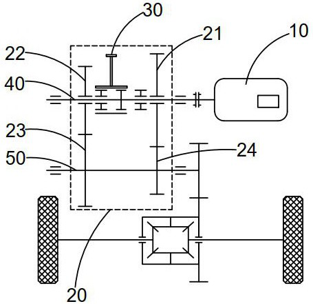
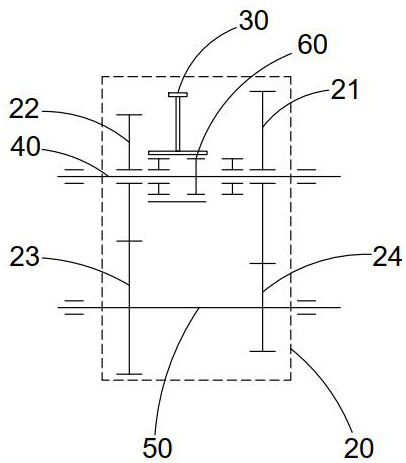
[0039] See attached manual Figure 1-4 shown, a two-speed transmission for new energy vehicles, including:

[0040] the first box 20,

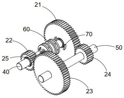
[0041] The first shaft body 40 , the first shaft body 40 passes through two opposite sides of the first box body 20 in sequence, and bearings are arranged at the joints. The second driving gear 22 and the first driving gear 21, the first shaft 40 between the second driving gear 22 and the first driving gear 21 is provided with a slidable shift assembly 60,

[0042] The second shaft body 50 , the second shaft body 50 passes through the two opposite sides of the first box body 20 in turn, and bearings are arranged at the joints, the second shaft body 50 is arranged parallel to the axis of the first shaft body 40 , and the second shaft body 50 A third driven gear 23 meshing with the second driving gear 22 and a fourth driven gear 24 meshing with the first driving gear 21 are provided,

[0043] Wherein, the second driving gear 22 and the first ...

Embodiment 2

[0057] This embodiment is further optimized on the basis of Embodiment 1 as follows: refer to the appendix of the description Figure 11 As shown, the side of the first driving gear 21 on which the first connecting block 70 is installed is provided with an auxiliary connecting ring 90, and the first connecting block 70 is connected with the side of the first driving gear 21 by fasteners. The connecting ring body 90 is arranged between the first connecting block 70 and the connecting side surface of the first driving gear 21 , the non-connecting part of the auxiliary connecting ring body 90 and the first connecting block 70 is bent upwards, and the bottom surface of the ring body is connected with the spring through the spring. The first driving gear 21 is laterally connected.

[0058] An auxiliary connecting ring body 90 is provided on the side of the second driving gear 22 on which the first connecting block 70 is installed. The first connecting block 70 is connected with the...

Embodiment 3

[0061] See attached manual Figure 1-4 shown, a two-speed transmission for new energy vehicles, including:

[0062] the first box 20,

[0063] The first shaft body 40 , the first shaft body 40 passes through two opposite sides of the first box body 20 in sequence, and bearings are arranged at the joints. The second driving gear 22 and the first driving gear 21, the first shaft 40 between the second driving gear 22 and the first driving gear 21 is provided with a slidable shift assembly 60,

[0064] The second shaft body 50 , the second shaft body 50 passes through the two opposite sides of the first box body 20 in turn, and bearings are arranged at the joints, the second shaft body 50 is arranged parallel to the axis of the first shaft body 40 , and the second shaft body 50 A third driven gear 23 meshing with the second driving gear 22 and a fourth driven gear 24 meshing with the first driving gear 21 are provided,

[0065] Wherein, the second driving gear 22 and the first ...


PUM


Abstract

The invention discloses a two-speed transmission for new energy vehicles, belonging to the field of new energy vehicle transmissions. The device comprises: a first case body, a first shaft body, and the first shaft body sequentially passes through two opposite sides of the first case body and Bearings are arranged at the connection, the first shaft body is provided with a second driving gear and a first driving gear respectively located in the two opposite inner wall directions of the first box body, and the first shaft body between the second driving gear and the first driving gear is arranged on the first shaft body Equipped with a slidable shift assembly, a second shaft body, the second shaft body is arranged in parallel with the axis of the first shaft body, and the second shaft body is provided with a third driven gear meshing with the second driving gear and The fourth driven gear meshed with the first driving gear, the present invention adjusts the reduction ratio through shifting, reduces the energy loss of the battery of the new energy vehicle, increases the cruising capacity, reduces the complexity of the transmission structure and the requirements of the manufacturing process, and can also Reduce the development difficulty and manufacturing cost of traction motors.

Description

technical field [0001] The invention belongs to the field of new energy vehicle transmissions, in particular to a two-speed transmission for new energy vehicles. Background technique [0002] The descriptions in this section merely provide background information related to the disclosure in the present application and do not constitute prior art. [0003] In recent years, due to increasingly severe environmental problems and soaring oil prices, more and more countries and OEMs have begun to pay attention to the development of pure electric vehicles. Pure electric vehicles are an important part of new energy vehicles. As the core part of the pure electric vehicle, the power transmission system has a great influence on the power and economy of the whole vehicle. Therefore, rationally selecting the components of the power transmission system and improving the efficiency of the power transmission system is one of the important means to improve the performance of electric vehic...

Claims


Application Information

Patent Timeline
Patent Type & Authority Patents(China)
IPC IPC(8): F16H3/083F16H63/30F16H61/04F16H57/04B60K17/08
CPCF16H3/083F16H63/30F16H61/04F16H57/0006F16H57/0416B60K17/08F16H2063/3093F16H2003/0818F16H2063/3089F16H2061/0474F16H2200/0021F16H2200/0034Y02T10/62
Inventor 陆林生
Owner 杭州骑遇科技有限公司
Why Eureka
Try Eureka