Gear shifting and parking locking mechanism for electric automobile

A technology for electric vehicles and parking locks, applied in mechanical equipment, transmission, transmission control, etc., can solve problems such as misoperation, danger, and damage to the locking mechanism, and achieve accurate shifting, avoid danger, and prevent the car from slipping. Effect

Pending Publication Date: 2021-12-03
SCANFIL HANGZHOU CO LTD
View PDF0 Cites 3 Cited by
  • Summary
  • Abstract
  • Description
  • Claims
  • Application Information

AI Technical Summary

Problems solved by technology

[0004] The purpose of the present invention is to provide a new energy vehicle shift and parking lock that can lock the output shaft of the transmission to prevent the car from slipping when parking, can protect the locking mechanism, and can avoid the danger caused by the driver's misoperation. In order to solve the problems in the above-mentioned background technology that the locking mechanism is prone to damage when the vehicle collides, and the driver's misoperation is likely to cause danger during the shifting process

Method used


Image

  • Gear shifting and parking locking mechanism for electric automobile
  • Gear shifting and parking locking mechanism for electric automobile
  • Gear shifting and parking locking mechanism for electric automobile

Examples


Embodiment 1

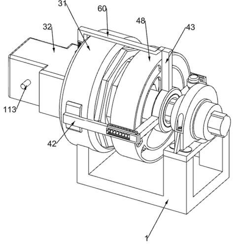
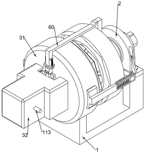
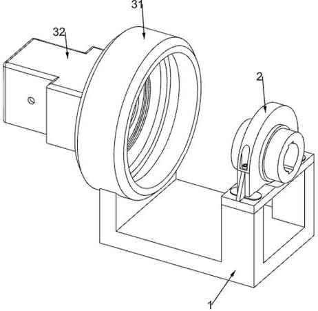
[0038] Gear shift and parking lock mechanisms for electric vehicles, such as figure 1 , figure 2 , image 3 , Figure 4 , Figure 5 , Figure 6 , Figure 7 , Figure 8 , Figure 9 , Figure 10 , Figure 11 , Figure 12 , Figure 13 , Figure 14 and Figure 15 As shown, it includes a bottom frame 1, a support seat 2, a support outer ring 31, a protective shell 32, a switching assembly 4, a speed change assembly 5 and a locking assembly 6. 1. A support outer ring 31 is fixedly installed on the upper left, and a protective shell 32 is fixedly installed on the left side of the support outer ring 31. A switching assembly 4 is arranged on the support seat 2. The switching assembly 4 is used to switch power, and the support outer ring 31 The upper rotation is connected with a transmission assembly 5, the transmission assembly 5 is used to control the driving speed of the car, and the locking assembly 6 is fixedly installed on the right side of the supporting outer ring ...

Embodiment 2

[0046] On the basis of Example 1, such as Figure 9 As shown, it also includes a trapezoidal locking tooth 2, a sliding locking tooth 2 8 and a second return spring 9, and the trapezoidal locking tooth 2 7 is connected to the outside of the slotted ring 63 in a circumferentially distributed manner, below the wedge-shaped sliding bar 60 Sliding type connection has sliding locking tooth 2 8, sliding locking tooth 2 8 is in contact with one of the trapezoidal locking teeth 2 7, sliding locking tooth 2 8 is used to block the trapezoidal locking tooth 2 7, sliding locking tooth 2 8 and wedge-shaped sliding bar 60 is connected with the second return spring 9.

[0047] When the driver parks the car, the situation that the trapezoidal locking tooth 1 66 may block the sliding locking tooth 1 67, the sliding locking tooth 1 67 cannot block the trapezoidal locking tooth 1 66, so the trapezoidal locking tooth 1 66 will slide the locking tooth When tooth 1 67 is blocked, the second homing...

Embodiment 3

[0049] On the basis of Example 2, such as Figure 11 , Figure 12 and Figure 13 As shown, it also includes an anti-tooth assembly 10, the slotted gear shaft 58 is provided with an anti-tooth assembly 10, the anti-tooth assembly 10 is used to protect the slotted ring 63 and its upper device, the anti-tooth assembly 10 includes a spline threaded shaft 101, a wedge-shaped fixing bar 102, a special-shaped slip ring 103 and a first return spring 104, and the slotted gear shaft 58 is connected with a spline threaded shaft 101 through a threaded connection, and the left side of the clamping rod 64 is fixed A wedge-shaped fixing bar 102 is connected, and a special-shaped slip ring 103 is slidably connected to the slotted gear shaft 58. The wedge-shaped fixing bar 102 is in contact with the special-shaped slip ring 103, and the special-shaped slip ring 103 is used to push the wedge-shaped fixing bar 102 and the clamp rod 64 to move relative to each other. , The special-shaped slip r...


PUM


Abstract

The invention relates to the technical field of new energy automobiles, in particular to a gear shifting and parking locking mechanism for an electric automobile. The gear shifting and parking locking mechanism for the electric automobile comprises an underframe, a supporting seat, a supporting outer ring, a protective shell, a switching assembly and the like, a supporting base is fixedly installed on the top of the right side of a bottom frame, a supporting outer ring is fixedly installed on the upper left portion of the bottom frame, a protection shell is fixedly installed on the left side of the supporting outer ring, and the switching assembly is arranged on the supporting base. Through cooperation of a first sliding clamping teeth and a second sliding clamping teeth, when an automobile is parked, the first sliding clamping teeth can clamp a first trapezoidal clamping teeth, or the second sliding clamping teeth clamp a second trapezoidal clamping teeth, so that a clamping rod clamps a slotting gear shaft, automobile wheels can be stably clamped, and automobile sliding caused by rotation of the wheels during parking is prevented.

Description

technical field [0001] The invention relates to the technical field of new energy vehicles, in particular to a shift and parking lock mechanism for electric vehicles. Background technique [0002] The current automatic transmission cars generally have a parking gear. In order to prevent the wheel from turning and causing the car to slip when parking, a parking lock mechanism will be installed in the automatic transmission, which is generally composed of a ratchet, a pawl, and a connecting shift lever mechanism. When the shift control handle is shifted to the parking gear, the parking mechanism will lock the output shaft of the transmission, so as to block the rotation of the transmission in neutral, so as to achieve the parking function. A good parking mechanism is the key to reliable parking of the car Means, when the gear is switched to a non-parking gear, the transmission output shaft output can be unlocked. [0003] The traditional parking lock mechanism has a complex s...

Claims


Application Information

Patent Timeline
Patent Type & Authority Applications(China)
IPC IPC(8): F16H61/32F16H61/18F16H63/34F16H63/30F16H37/08
CPCF16H61/32F16H61/18F16H63/3425F16H63/3433F16H63/304F16H37/082F16H2061/2876
Inventor 彭雪梅
Owner SCANFIL HANGZHOU CO LTD
Why Eureka
Try Eureka