
Experimental device for frictional loss between high-strength high-speed rail contact wire and pantograph

A contact wire and friction loss technology, which is applied in the field of experimental devices for friction loss between high-strength high-speed rail contact wires and pantographs, can solve problems such as pantograph constraints, and achieve a high degree of improvement, strong practicability, and simple structure. Effect

Active Publication Date: 2021-12-03
JIANGSU MEILIN COPPER
View PDF8 Cites 1 Cited by
  • Summary
  • Abstract
  • Description
  • Claims
  • Application Information

AI Technical Summary

Problems solved by technology

[0003] Aiming at the wear and tear problem of pantograph components, there are various online high-definition camera detection components, and there is also an effective method for detecting wear by using cross-sectional resistance and current methods disclosed in CN 108981556 B. However, these detection They are all based on pantographs that have been used for a long time. When researching the wear of contact wires and pantographs in the laboratory, it is necessary to collect the pantographs used for external installation, and to study the new structure and materials of pantographs. R&D poses significant constraints and requires an experimental setup that facilitates laboratory-based sampling studies of friction losses between the high-speed rail contact wire and the pantograph

Method used


Image

  • Experimental device for frictional loss between high-strength high-speed rail contact wire and pantograph
  • Experimental device for frictional loss between high-strength high-speed rail contact wire and pantograph
  • Experimental device for frictional loss between high-strength high-speed rail contact wire and pantograph

Examples


Embodiment 1

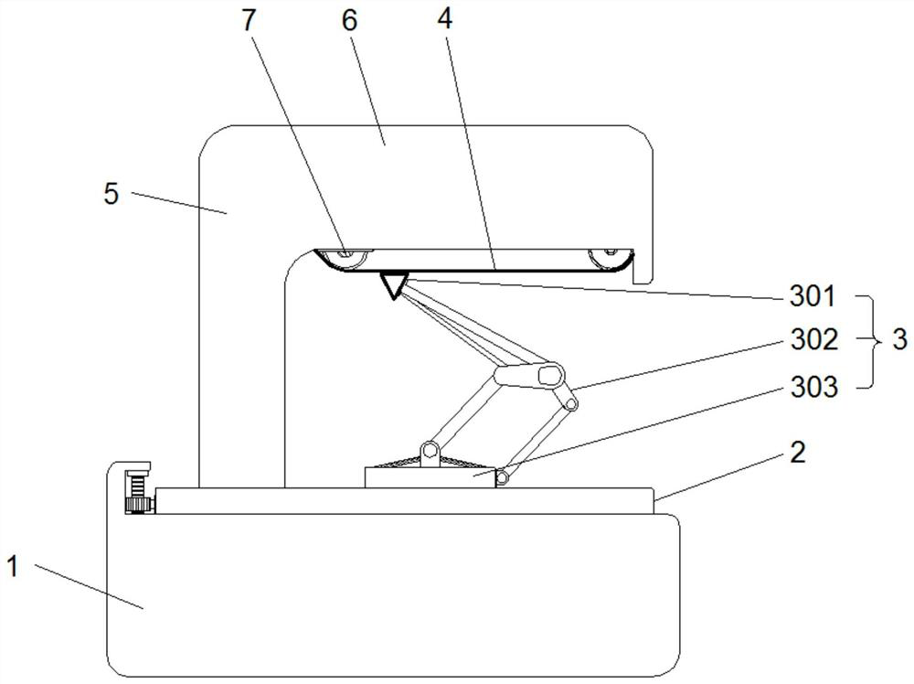
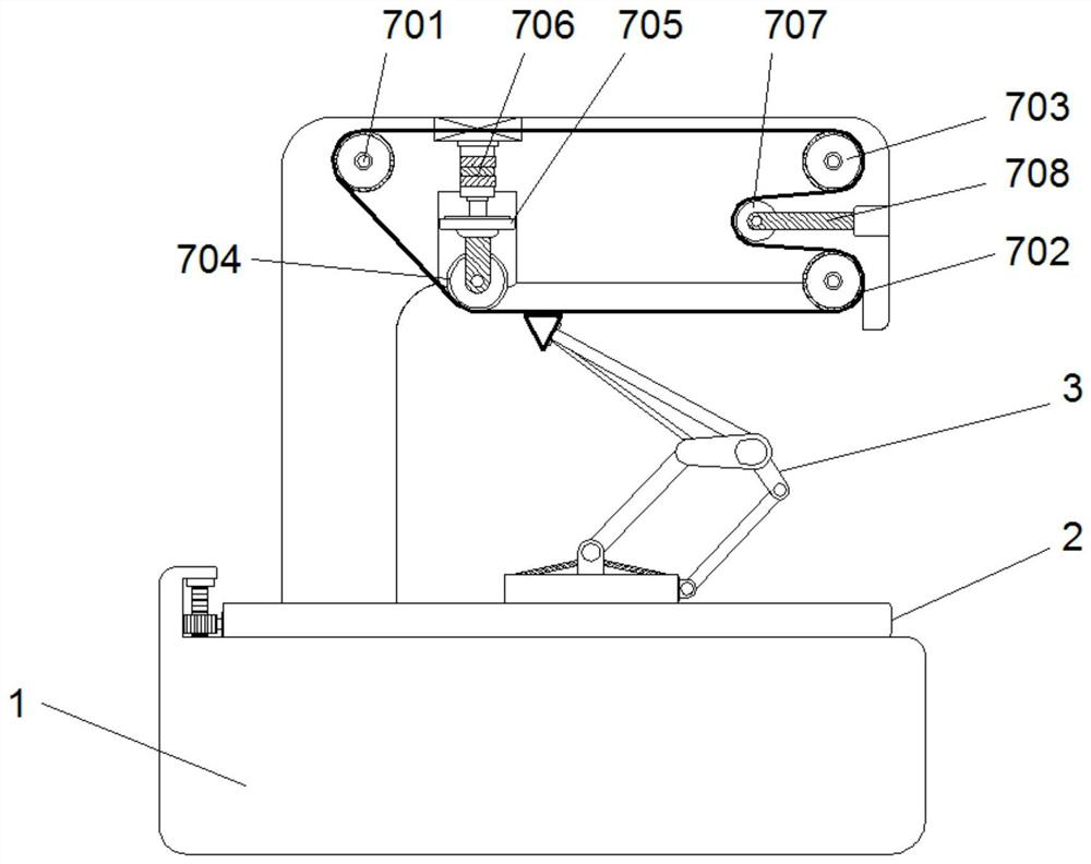
[0030] See Figure 1 ~ 4, Embodiments of the present invention, high strength and high iron contact wires and frictional losses between the experimental apparatus by a pantograph, comprising a base 1, an upper end of the base 1 is provided with a platen for placing test pantograph assembly 3 2, receiving the base 3 of the pantograph assembly 303 fixed to the platen 2 in the experimental holding the upper end surface of the slider 3 pantograph assembly 301 fixed to the base 303 of the upper end, the upper end of the slider 301 by contacting the support with a test lead boom 4 302, the experiments lead top plate 6 is mounted in the rotational direction of the transmission conductors 3 opposite to the conducting component pantograph assembly 7, the conducting wire assembly 7 mounted on a machine base 4, the top plate 6 is fixed by the stand 5 provided on the base 1, experiments lead wire 4 is driven transporting unit 7 and the high speed rotation and continuous frictional contact with...

Embodiment 2

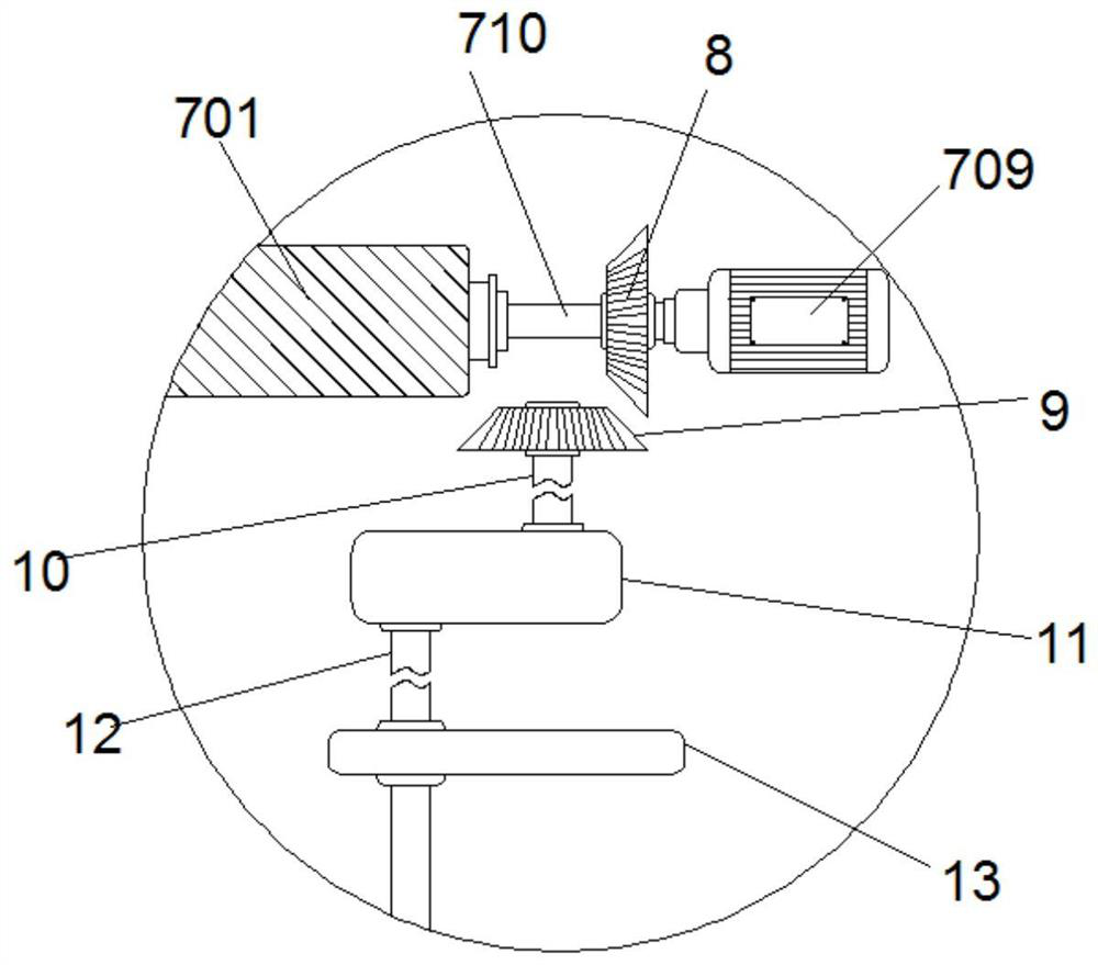
[0039] See Figure 5 ~ 7 Travel, embodiments of the present invention, in Example 1, to further enhance the high strength and high iron contact wires and the degree experimental frictional losses between the pantograph analog high-speed travel during work, so that the pantograph assembly 3 is subjected to simulated Britain woman on the line, vibration, in particular:

[0040] The base 1 is also provided with conducting wire 7 synchronizing component, high-speed analog encounter bumps, the shock bumps vibrating assembly situation, the experiment can be provided with vertically movable upper platen 2 movable plate 203, by pantograph assembly 3 is provided with an elastic material fixed to the clamping plate 204 in contact with the lower end surface of the movable plate, the movable plate 203 is 203, the contact plate 204 is provided below the box 23 pushing, pushing down box 23 may be disposed below the contact plate 204, pushing the box 23 with the contact plate 204 spaced apart, pu...

Embodiment 3

[0045] On the basis of the first embodiment, the embodiment of the present invention is upgraded to the experimental device of the high-intensity high-speed rail contact wire and the electrical shift loss, specifically:

[0046] The first rotating shaft 710 in the wire instruction assembly 7 also has a data acquisition device, which is a speed detector, a mileage detector, a timer, and the like, and integrated through an existing speed, mileage. Get the speed and total mileage of the friction of the electroded arch assembly 3 and the experimental wire 4, which is easy to provide the necessary data parameters to subsequent friction loss experiments to ensure the accuracy of the experiment.


PUM


Abstract

The invention discloses an experimental device for a frictional loss between a high-strength high-speed rail contact wire and a pantograph. The device comprises a base, an experimental bedplate for placing a pantograph assembly is arranged at the upper end of the base, and an experimental wire is mounted on a wire transmission assembly of which the rotation transmission direction is opposite to the pantograph assembly. A transverse swing assembly which synchronously acts along with the wire transmission assembly and simulates left-right swing of the high-speed rail during advancing is arranged in the base, a jolting and vibrating assembly which synchronously acts along with the wire transmission assembly and simulates jolting and vibrating of the high-speed rail is further arranged in the base, and high-speed transmission of experimental wires in a closed loop is achieved through the wire transmission assembly. Within a limited operation range, a required friction loss experiment research sample is quickly and efficiently formed, swinging and jolting vibration borne by a high-speed rail carriage in the running process are simulated through the transverse swinging assembly and the jolting vibration assembly, the abrasion degree of a pantograph assembly and an experiment wire is improved, and the friction loss experiment between the high-strength high-speed rail contact wire and the pantograph can be conveniently carried out.

Description

Technical field [0001] The present invention relates to the field of experimental apparatus, the experimental apparatus is particularly high strength and frictional wear between the contact wires and iron pantograph. Background technique [0002] Pantograph is acquired electric power from the electric traction locomotives catenary electrical equipment, mounted on the roof of an electric traction locomotives, high-iron as a high-speed train, which uses the electric drive, during traveling at high speed, the traction motors convert electrical energy into mechanical energy, a high-speed efficient and reliable power source, and therefore, the high-speed rail carriage is also equipped with a pantograph assembly, slide pantograph assembly typically telescopic bracket supporting the upper end thereof in contact with the electrical contact line, pantograph assembly, especially it tends to slide as a contact portion for wear inevitably, in particular mounted on the vehicle speed up to 300...

Claims


Application Information

Patent Timeline
IPC IPC(8): G01N19/02
CPCG01N19/02
Inventor 李小武翟金勇邵云林
Owner JIANGSU MEILIN COPPER
Learn More